机器人应用

turtlebot移动机器人(23):真实环境定位导航

Building a Map

TurtleBot maps are build with gmapping. You can tweak this algorithm by modifying parameters on launch/includes/_gmapping.launch file.

First, you need to start the robot drivers ,
and then start the ROS node responsible for building the map.

It has to be noted that to build a map ROS uses the gmapping software package, that is fully integrated with ROS.
The gmapping package contains a ROS wrapper for OpenSlam’s Gmapping. The package provides laser-based SLAM (Simultaneous Localization and Mapping), as a ROS node called slam_gmapping.
Using slam_gmapping, you can create a 2-D occupancy grid map (like a building floorplan) from laser and pose data collected by a mobile robot.

On terminals:
$ roscore
$ roslaunch turtlebot_bringup minimal.launch
$ roslaunch turtlebot_navigation gmapping_demo.launch

Move the robot :
$ roslaunch turtlebot_rviz_launchers view_navigation.launch
$ roslaunch turtlebot_teleop keyboard_teleop.launch

save the built map :
$ rosrun map_server map_saver -f /tmp/my_map

will generate two files with the name you specified in the map_server commnd.
So in this case, the two files’ names are my_map.pgm and my_map.yaml.
If you open the .yaml file you will see something like this:

image: /tmp/my_map.pgm
resolution: 0.050000
origin: [-12.200000, -12.200000, 0.000000]
negate: 0
occupied_thresh: 0.65
free_thresh: 0.196

The .yaml contains meta data about the map, including the location of image file of the map, its resolution, its origin, the occupied cells threshold, and the free cells threshold. Here are the details for the different parameters:
* image: has a pgm format which contains numeric values between 0 and 255. It represents the path to the image file containing the occupancy data; can be absolute, or relative to the location of the YAML file
* resolution: it is the resolution of the map and is expressed in meters/pixel, which means in our example 5 centimers for each cell (pixel).
* origin: The 2-D pose of the lower-left pixel in the map, as (x, y, yaw), with yaw as counterclockwise rotation (yaw=0 means no rotation). Many parts of the system currently ignore yaw.
* occupied_thresh: Pixels with occupancy probability greater than this threshold are considered completely occupied.
* free_thresh: Pixels with occupancy probability less than this threshold are considered completely free.
* egate : Whether the white/black free/occupied semantics should be reversed (interpretation of thresholds is unaffected)

Now, for the second file, that is the .pgm image file, it is just a gray-scale image of the map which you can open using any image editor program
It is recommended to use the The GNU Image Manipulation Program to open and edit PGM files.

The gray area represents an unknown non-explored space.
The white area represents the free space,
and the black area represents obstacles (e.g. walls).

You can open this file with any text editor like gedit or kate to see its content.
In what follow, we present the four first lines of a typical pgm file :

P5
# CREATOR: GIMP PNM Filter Version 1.1
600 600
255

The first line, P5 identifies the file type.
The third line identifies the width and the length in number of pixels.
The last line represents the maximum gray scale, which is this case 255 that represents the darkest value. The value 0 in a PGM file will represent a free cell.

desription of turtlebot_navigation gmapping_demo.launch:

First it starts the 3dsensor launch file which will runs either Asus Xtion Live Pro or Kinect 3D sensor of the Turtlebot.
It sets some parameters to their default values and specifies that the scan topic is refered to as /scan.
Then, it will start the gmapping.launch.xml that contains the specific parameters of the gmapping SLAM algorithm (parameters of the particle filter) that is responsible for building the map.
Finally, it will start the move_base.launch.xml that will initialize the parameters of the navigation stack, including the global planner and the local planner.

Practical Considerations

When building a map with a Turtlebot it is possible to get a good or bad map depending on several factors:
First of all, make sure that your Turtlebot robot and its laptop have full batteries before starting the mapping tasks. In fact, gmapping and rviz both consume a lot of power resources.

The quality of the generated map greatly depends on quality of range sensors and odometry sensors. For the Turtlebot, it has either the Kinect or Asus Xtion Live Pro camera with only 4 meters of range, and only 57 degree of laser beam angle, which render it not appropriate for scanning large and open space environments. Thus, if you use Turtlebot to build the map for a small environment where walls are not far from each others, it is likely that you will get an accurate map.

However, if you build the map for a large and open space environment, then it is likely that your map will not be accurate at a certain point of time. In fact, in large and open space environment, you need to drive the robot for long distance, and thus, the odometry will play a more cruicial role in building the map. Considering the fact that the odometry of the Turtlebot is not reliable and is prone to errors, these errors will be cumulative over time and will quickly compromise the quality of generated maps.
It will interesting to try using your Turtlebot to build maps for both small environment and large environment and observe the accuracy of the map for each case.

ADCANCED

gmapping package:

This package contains a ROS wrapper for OpenSlam’s Gmapping. The gmapping package provides laser-based SLAM (Simultaneous Localization and Mapping), as a ROS node called slam_gmapping. Using slam_gmapping, you can create a 2-D occupancy grid map (like a building floorplan) from laser and pose data collected by a mobile robot.
slam_gmapping package: slam_gmapping contains a wrapper around gmapping which provides SLAM capabilities.

To use slam_gmapping, you need a mobile robot that provides odometry data and is equipped with a horizontally-mounted, fixed, laser range-finder.
The slam_gmapping node will attempt to transform each incoming scan into the odom (odometry) tf frame.

For Example To make a map from a robot with a laser publishing scans on the base_scan topic:
$ rosrun gmapping slam_gmapping scan:=base_scan

10-mapping

(1) ssh to On TurtleBot :
$ roslaunch turtlebot_bringup minimal.launch
$ roslaunch turtlebot_navigation gmapping_demo.launch

(2) On local workstation :
$ roslaunch turtlebot_rviz_launchers view_navigation.launch
$ roslaunch turtlebot_teleop keyboard_teleop.launch

(3) using teleoperation from local machine, navigate TurtleBot around the entire area you wish to map

(4) if complate, using ssh to save the map on remote robot:
$ rosrun map_server map_saver -f map_file:=/home/dehaou1404/zMAP/my_map_half.yaml
NOTE: not use relative sunch as ~, use /home…

(5) you can find the map and yaml
$ ls /tmp/

turtlebot移动机器人(21):模拟器的定位导航

在hydro版本的ROS,对于turtlebot机器人,只支持stage模拟器,栈和包是turtlebot_gazebo。

0、准备

0.1、如果需要,安装:
$ sudo apt-get install ros-hydro-turtlebot-simulator
0.2、如果需要,更新:
$ rosdep update
0.3、如果需要安装键盘控制
$ sudo apt-get install ros-hydro-turtlebot-apps ros-hydro-turtlebot-rviz-launchers

一、仿真:gazebo模拟world,rviz可视化。

1.1、启动gazebo模拟器下的机器人,和空的world。
$ roslaunch turtlebot_gazebo turtlebot_empty_world.launch
1.2、启动键盘控制终端,这样可以通过键盘控制机器人动作。
$ roslaunch turtlebot_teleop keyboard_teleop.launch
1.3、启动可视化窗口,这样可以显示机器人所探测的世界。
$ roslaunch turtlebot_rviz_launchers view_robot.launch
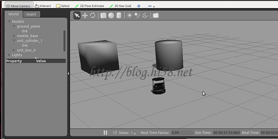
1.4.1、可以在gazebo里面放置一些障碍物,例如圆柱垃圾桶和矩形桌子

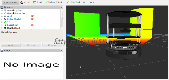
1.4.2、通过rviz,可以显示点云图

二、建图导航:进一步的建图和导航功能。

1.1、启动gazebo模拟器下的机器人和虚拟world
$ roslaunch turtlebot_gazebo turtlebot_playground.launch
1.2、启动建图
$ roslaunch turtlebot_gazebo gmapping_demo.launch
1.3、通过可视化查看建图过程
$ roslaunch turtlebot_rviz_launchers view_navigation.launch
1.4、启动键盘控制终端移动,直到地图满意为止
$ roslaunch turtlebot_teleop keyboard_teleop.launch
1.5、保存地图
$ rosrun map_server map_saver -f ~/demomap
1.6、使用地图导航:关闭所有进程,重复以上所有步骤,除了建图这一步。
$ roslaunch turtlebot_gazebo amcl_demo.launch map_file:=~/demomap.yaml

  • 1、启动机器人

物理环境就是把真是机器人bring-up,这里在3d版模拟器gazebo中启动机器人turtlebot:
$ roslaunch turtlebot_gazebo turtlebot_world.launch
先启动这个gazeb就相当于把硬件启动了,传感器也都启动了,激光器/scan和里程计/odom都有数据了。
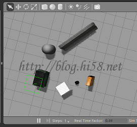
如下图这是个简单的宾馆场景:

问题一、出现Error [SDF.cc:788] Missing element description for [pointCloudCutoffMax]
解释:没找到答案。好像不会影响使用。
问题二、出现modeldatabase:unable to get model name
解释一:这是gazebo2.2太老,需要更新:
$ sudo sh -c ‘echo “deb http://packages.osrfoundation.org/gazebo/ubuntu trusty main” > /etc/apt/sources.list.d/gazebo-latest.list’
$ wget http://packages.osrfoundation.org/gazebo.key -O – | sudo apt-key add –
$ wget http://gazebosim.org/models/dumpster/model.tar.gz
解释二:这是因为它到http://gazebosim.org/models去采集组建但某种原因出现了问题,所以不如直接全部下载,几个小时。
$ cd ~/.gazebo
$ wget -r -R “index.html*” http://models.gazebosim.org/
把下载得到的都复制到~/.gazebo/models文件夹。
问题三、启动gazebo出错不能启动
解释:这通常是非nvida显卡引起的,没有办法,多启动几次总会好。

  • 2、控制机器人移动

如果通过键盘
$ roslaunch turtlebot_teleop keyboard_teleop.launch –screen
如果通过罗技手柄
$ roslaunch turtlebot_teleop logitech.launch –screen

3、查看机器人

$ roslaunch turtlebot_rviz_launchers view_robot.launch
很好,机器人看起来不错。

4、创建地图

$ roslaunch turtlebot_gazebo gmapping_demo.launch
启动gmapping,就可以利用采集所得到的传感器数据,进行地图绘制,/map也就有数据了。
这个过程是静寂的。
说明一、这个terminal停留在Registering First Scan不动,这是因为机器人没有移动的缘故。
此时可以尝试调试工具:
$ rosrun rqt_graph rqt_graph
WARNING: topic [/base_scan] does not appear to be published yet

5、显示地图

Gazebo模拟了现实世界,RViz可视化的感知周围事物。所以运行rviz,显示相应的制图信息。
$ roslaunch turtlebot_rviz_launchers view_navigation.launch –screen
此时可以尝试调试工具:
$ rostopic echo /base_scan
$ rostopic echo /odom
$ rostopic echo /map | grep frame_id
$ roswtf
$ Loaded plugin tf.tfwtf No package or stack in context
根据激光扫描器安装与否,有时会把scan重定向到base_scan,这样:
$ rosrun gmapping slam_gmapping scan:=base_scan

6、移动扫描

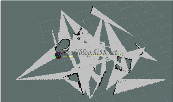
此时控制turtle平面走动,并转圈扫描,不断丰富地图,如下图:

  • 7、保存地图

如果满意,把地图保存用于后续的导航:
$ rosrun map_server map_saver -f dehaoZ_map

8、建图结束

地图构建完成后,关闭以上所有进程。看机器人如何自主导航。

启动硬件模拟器

$ roslaunch turtlebot_gazebo turtlebot_world.launch

键盘或手柄的teleop控制可选

$ roslaunch turtlebot_teleop keyboard_teleop.launch –screen

启动导航

$ roslaunch turtlebot_gazebo amcl_demo.launch map_file:=/home/dehaoz/dehaoZ_map.yaml
这个过程也是静寂的。

可视化查看它的导航过程

$ roslaunch turtlebot_rviz_launchers view_navigation.launch

随便点击,作为目标地。规划路径及行走过程如下图:

amcl的terminal里也会提示到达目的地:

9、琐碎的事情

问题一、
rviz出错:Map “No transform from [map] to [base_link]”
解释:
You will need a transform from the /map frame to /base_link. However, there only needs to be a path between /map and /base_link, not a direct transform. Usually, the transform setup looks something like /map->/odom->/base_link.
These transforms are usually provided by a localization node such as amcl or a SLAM node such as gmapping.

问题二、
rviz出错:global status error Fixed Frame [map] does not exist
解释一、
I may not be considering this correctly, but it may be as simple as changing your “fixed frame” under “.Global Options” to “/”, “/world”, or some
fixed frame that you do have a transform for. “/base_link”!!!!
解释二、
1-这个fix frame可以解决I don’t even know how to change it. I tried your solution, it fixes “Global Status” but there still is RobotModel error:
Screenshot rosrun tf static_transform_publisher 0.0 0.0 0.0 0.0 0.0 0.0 map my_frame 100
2-You don’t have a localization as e.g. amcl running. Thus, the transformation map->base_link (or whatever you have for your robots link) does not
exist.
解释三、
You need to publish a map frame. If I’m correct, your problem is that AMCL is looking for the /map frame when it loads your static map from the map_server. In order to resolve this problem, you must either set the frame_id of your map_server to /odom or publish the /map frame as a parent
frame to /odom.

问题三、
amcl出现Extrapolation Error looking up robot pose: Lookup would require extrapolation into the past. Requested time 560.090000000 but the earliest
data is at time 620.530000000, when looking up transform from frame [base_footprint] to frame [map]
解释一、
The error is telling you that your asking for a transform from a time before which you have tf data。Most tf datasources report data in monotonic
increasing order which means that no matter long you wait you will not receive older data.。You will either need to initialize the transform listener
earlier and allow the buffer to fill up, or pass a few of these errors on startup. It’s a common race condition whether the data or tf data arrives
first.。try increasing ros::Duration(0.2) upto maximum of 10 seconds。就是说要增加延时,或者采用阻塞模式:
try{
ros::Time now = ros::Time::now();
listener.waitForTransform(“/turtle2”, “/turtle1”,now, ros::Duration(3.0));
listener.lookupTransform(“/turtle2”, “/turtle1”, now, transform);
//Note: Using ros::Time::now() is for demo, usually would be timestamp of data wishing to be transformed.
这里面waitForTransform()将会阻塞一直到坐标转换可用为止或者超时为止。
诊断二、
warn:could not get robot pose
(1)先看看大致结构。
$ rosrun rqt_graph rqt_graph
(2)再看看tf信息
$ rosrun tf tf_monitor
(3)可能会有
published by unknown_publisher
(4)看看amcl
$ rostopic info amcl_pose
(5)可以尝试
$ rosrun tf tf_echo odom map
(6)尝试减小地图尺寸
reducing size of local cost map to original size of 6×6 @ 0.5 resolution, the extrapolatoin error went away.
(7)注意CPU负载
$ gnome-system-monitor
To make sure the CPU didn’t stall, I essentially lowered the local/global maps and move_base controller update frequency to a point where the
navigation wouldn’t work well at all. For me, the map updating/publishing rates were down to 3Hz and 2Hz, respectively. The move_base frequency was
also down to 3-4Hz. On top of this, I was running rviz on the same laptop on an integrated graphics card.
1-The local planar detected an obstacle. As it moves around it, the obstacle was dragged across the local map, enclosing the robot an completely
unmovable space.
2-This lead to the robot getting lost, a lot. I would see it moving to the goal designated, but when it gets there, it would spin to get the correct
orientation. While this happens, the laser scan would slowly move out of place of the global map.Here is a couple general rule of thumb if you want
to run the navstack:Don’t run the map/controller frequency lower than the ros nav stack guide.I upgraded to a laptop with an i7-4th gen (~2.2Ghz),
and an nvidia graphics card. I run the map publish rates and controller publish rates to twice the ros tutorial’s values. It can run at higher
velocities and smoother motions!Naturally, those errors went away after the upgrade and the CPU stopped stalling/running so slow.
解释三、
是真实导航但可能使用了模拟位置:
The problem is your fake_localization. It publishes map->odom, which is now done by the real localization from the MultiMapper, So you have to remove
this fake_localization.
Somewhere in your launch file there is a node named “fake_lokalization” (I guess it is just a static_transform_publisher). Just remove this one when
adding the mapper to your system.
Looking at your RVIZ-screenshot it seems a bit like the robot is not moving the way it thinks it does. (The map patches are overlayed incorrectly.)
Some ideas only:
Check if the odometry published by Gazebo is correct. (Visualize TF in RVIZ)
Look at the Operators costmap in RVIZ (type “map”, topic “/Operator/local_costmap”)
Try to run tutorial 1 with your setup first and see if it works correctly. Then add Mapper and Navigator step by step.

turtlebot移动机器人(19):kobuki底盘的驱动

Useful for compatibility checking and introspection.
$ rosrun kobuki_driver version_info

PART I installtion

This instruction describes how to install Kobuki ros packages and get you ready to play with Kobuki.

1. Install Kobuki
$ sudo apt-get install ros-indigo-kobuki ros-indigo-kobuki-core

2. Set udev Rule
Copy across a udev rule for /dev/kobuki port and add your user to the dialout group (you may need to log out and log back in).
Connection to the kobuki base is via usb enabled by an ftdi usb-serial converter which is always pre-flashed at the factory with the serial id kobuki. For convenience, to enable the device to appear on /dev/kobuki, use the following script to copy across the udev rule and restart udev (you’ll need your sudo password):
$ rosrun kobuki_ftdi create_udev_rules

NOTE for none ros users:
In case you are not in a ROS environment, you will need to build the package first, in order to get the create_udev_rules script.
To do so navigate to the package folder and do
$ make udev

3. Keyboard Teleoperation
Ready to rock! With all the software you have installed so far, you should be able to teleoperate your kobuki around with your keyboard!

# This launches the minimal operation configuration
$ roslaunch kobuki_node minimal.launch

# This launches the keyboard teloperation node
$ roslaunch kobuki_keyop keyop.launch

PART II Inspection

Inspect the sensors’ state and send commands.

1. start minimal.launch to bring up Kobuki’s basic software (bootstrap layer). We use the argument –screen to get verbose output in the terminal.
> roslaunch kobuki_node minimal.launch –screen

2. take a look at Kobuki’s topics.
$ rostopic list
/sensor/: Continuous streams of the sensor’s data (note that /odom and /joints_states are remapped by default, since they are widley used at the highest level/namespace)
/events/: If a sensor changes its state, e.g. bumper pressed/released, the new state is published here.
/commands/: Use these topics to make Kobuki do things like switch on LEDs, playing sounds and driving around.
/debug/: Outputs detailed info about a lot of Kobuki’s internals.

3. Check sensors
$ rostopic echo /mobile_base/events/bumper
state: 1
bumper: 2
$ rostopic echo /mobile_base/events/wheel_drop
state: 1
wheel: 0

$ rostopic echo /mobile_base/sensors/imu_data
header:
seq: 0
stamp:
secs: 1355022789
nsecs: 36483345
frame_id: gyro_link
orientation:
x: 0.0
y: 0.0
z: 0.28769484546
w: 0.957722128749

Change the color or turn off a LED:
$ rostopic pub /mobile_base/commands/led1 kobuki_msgs/Led “value: 1”
$ rostopic pub /mobile_base/commands/led1 kobuki_msgs/Led “value: 0”

Play a sound:
$ rostopic pub /mobile_base/commands/sound kobuki_msgs/Sound “value: 6”

PART III Manupulation

Make it move

$ roslaunch kobuki_node minimal.launch –screen
$ roslaunch kobuki_keyop safe_keyop.launch –screen
There is also a normal keyop launcher (keyop.launch). The difference between both is, that safe_keyop makes use of a velocity smoother and Kobuki’s safety controller.

PART IV automatic docking

This tutorial will show you how to run automatic docking with kobuki, and will give you a brief description of algorithm. The code is located in kobuki_auto_docking package.

To run automatic docking properly, docking station should be placed in an open space of at least 2 meters wide by 5 meters long. There should be no obstacles between kobuki robot and docking station. And the dock station should be held by a wall or something heavy enough to prevent the robot to push it. A static red light on top of the docking station signals that it is powered on properly.

If you already launched kobuki_node, load the auto-docking nodelet into the running kobuki core. For convenience, just type:

$ roslaunch kobuki_auto_docking minimal.launch –screen
Or if you have not launched the kobuki core yet, type:
$ roslaunch kobuki_auto_docking compact.launch –screen
Be aware that this is just loading the algorithm; it is still not active. The algorithm is implemented as a typical action server. You need to call the server via an action client.

To activate it type:
$ roslaunch kobuki_auto_docking activate.launch –screen

Kobuki’s docking station has 3 IR(Infrared) emitters. The emitted IR lights cover three regions in front of the docking station: left, central and right, each divided in two sub-fields: near and far. Each beam encodes this information, so the robot knows at any moment in which region and sub-field he is. Also, as regions and fields are independently identified, they can be overlap on its borders.

Kobuki has 3 IR receivers. When the robot is placed within the field of the docking station, and at least one IR receiver is facing toward it, the robot will catch the signal and stream it to the controller netbook. The information is available on /mobile_base/sensors/dock_ir topic, in the form of kobuki_msgs/DockInfraRed messages

PART V Kobuki’s Control System

A note on Nodelets
Nodelets are heavily used in Kobuki’s control system. They have various benefits over normal nodes. The most important among them are avoiding serialising/deserialising of messages and the transmission over the TCP/IP. This is done by passing pointers to messages instead of the messages themselves. That means messages are faster processed and transmitted. When working with big messages, such as point clouds, this can also significantly lower the CPU consumption.

For our use case, the speed improvement is important, that is why we implement controllers and other speed-sensitive parts of Kobuki’s control system as nodelets.
Implementing code as nodelets instead of node is nothing to be afraid of as the the next tutorial will show.

Kobuki’s control system uses three different components.

kobuki_node: (AKA mobile base) is actually a nodelet, which wraps the C++ driver for communicating with Kobuki
cmd_vel_mux: is a velocity command multiplexer (or in otherwords a switch). It manages multiple incoming velocity commands according to the configured priority.
Kobuki controller: is a nodelet-based controller type – used for various applications; one example is the kobuki_safety_controller, which watches the bumper, cliff and wheel drop sensors and acts accordingly. Use this to implement your own reactive controller (see the next tutorial).
Furthermore, there is an implementation of a velocity smoother: yocs_velocity_smoother. This tool is optional, but highly recommended to use. In case a node publishing velocity commands can’t ensure their smoothness, put this smoother in between that node and the cmd_vel_mux.

The three components introduced above are used in a small hierarchy. Starting bottom-up, there is the mobile base, which listens for commands (LEDs, sounds, velocity) and publishes sensor information. On top of that we use the cmd_vel_mux, which makes sure, that only one velocity command at a time is relayed through to the mobile base. On the next level we have one or more controllers and other programs, such as keyboard teleop and the navi stack. There are cases, in which we want smooth velocity (e.g. keyop) and cases in which we don’t (safety controller). So, use the velocity smoother when necessary.

In the shown scenario, there are multiple programs, which want to control Kobuki’s movement. The velocity muxer allows using all of them in parallel. An example multiplexer configuration could be the following:
Priorities:
3 (highest priority): safety controller
2: keyboard teleop
1: android teleop
0 (lowest priority): navi stack teleop
In this case, the navi stack would control the robot in most of the times. However, the user can override navi stack’s commands, by triggering commands with the Android teleop app or the keyboard teleop. In case both teleops would be active at the same time, keyboard teleop would win. However, all the velocity commands above will be overridden when the safety controller kicks in (bumper, cliff or wheel drop sensor activated). This allows safe driving of Kobuki with all three tools.

IMG
https://docs.google.com/drawings/pub?id=1AP_T-5yWtVKxe981M7h8I9Paxd8gfzGIqvLZEudCG9k&w=750&h=1091

CHAPTER VI write nodelet

how to write and run a simple nodelet-based controller for Kobuki.

In this section we will create a simple “blink, when a bumper is pressed” controller, which will be similar to the Kobuki’s safety controller.

You find the code explained in the following paragraphs in the kobuki_controller_tutorial package. We will also make use of the default controller from yocs_controllers.

First create a new package for this controller in your workspace. We use roscreate-pkg to add the dependencies right away:
$ catkin_create_pkg kobuki_controller_tutorial roscpp yocs_controllers std_msgs kobuki_msgs nodelet

REF: https://charlyhuangrostutorial.wordpress.com/category/ros%E8%87%AA%E5%AD%B8%E7%AD%86%E8%A8%98/

turtlebot移动机器人(17):参数化