智能机器人(23):Hokuyo 激光雷达Laser Sensor

II — Adding a Hokuyo Laser to your Turtlebot – URG
This assumes that you have a TurtleBot which has already been brought up.
1. Setup udev
Create the file /etc/udev/rules.d/50-laser.rules, add the following to it:
KERNEL==”ttyACM[0-9]*”, MODE=”0777″
or,
$ sudo echo ‘KERNEL==”ttyACM[0-9]*”, MODE=”0777″‘ >> /etc/udev/rules.d/50-laser.rules
Restart udev to take on the new rules with:
$ sudo /etc/init.d/udev restart
2. Now plug in your laser.
Check it’s file permissions. They should be read/write/execute for all.
Start by listing the permissions of the Hokuyo:
$ ls -l /dev/ttyACM0
— crw-rw-XX- 1 root dialout 166, 0 2009-10-27 14:18 /dev/ttyACM0
If XX is rw: the laser is configured properly, if not:
$ sudo chmod a+rw /dev/ttyACM0
3. Edit your turtlebot description
$ roscd turtlebot_description
Edit ./urdf/turtlebot_library.urdf.xacro , add the laser to the robot model, add the following right above the tag

NOTE:
The stock files will have your kinect’s virutal laser scan publishing on the same topic that other tutorials want to use,
and I would rather the laser data would come from the hokuyo laser.
This can be prevented by changing the topic that the Kinect laser publishes on with the following:

$ vi turtlebot_bringup/launch/3dsensor.launch
edit 3dsensor.launch and look for the line that looks like this:

Remove it and replace it with:

Then edit minimal.launch, for we now need to add the hokuyo node to it.
At the bottom of the file right before , add the following:

This should bring up the hokuyo node when you launch it.

4. Bringup your new config
$ roslaunch turtlebot_bringup minimal.launch
— process[laser_driver-9]: started with pid [8288]

In another terminal, you can bring up the kinect sensor by running:
$ roslaunch turtlebot_bringup 3dsensor.launch

5. Check your results with rviz
Now run rviz. You should now have a block that appears on your turtlebot.
Add two LaserScan visuilizations.
Subscribe one of them to the /kinect_scan topic and set it’s Color to “2; 255; 255”
Subscribe the other topic to /scan. Leave it’s Color “255; 255; 255″

III — Adding Hokuyo Laser Range Finder to Turtlebot
Keyword: Hokuyo Node (UTM-04G)

Add Hokuyo laser range finder (LRF) sensor to TurtleBot, explains how to write URDF description of the Hokuyo LRF, modify the URDF of the Turtlebot robot to account for the addition of the Hokuyo sensor.
Hokuyo LRF added on top of the Turtlebot.
http://www.iroboapp.org/index.php?title=File:Hokuyo_Turtlebot.jpg

1 Hokuyo-Related Pre-required
UTM-04G is a laser scanner that can scan with an opening up to 270 degrees with a range up to 4 meters.
Alough TurtleBot comes with the Kinect sensor that has a laser scanner with a scan opening up to 57 degrees with practical range of 3 meters.
Hokuyo LRF is more accurate than the Kinect sensor and it would be more useful in making maps with gmapping and SLAM applications.

ROS provides a driver for Hokyuo LRF, referred to as urg_node, install the urg_node as follows:
$ sudo apt-get install ros-indigo-urg-* <— this is special for URG class It is also possible to use the hokuyo_node and for this you need to install hokuyo_node as follows: $ sudo apt-get install ros-indigo-hokuyo-node Here we used later Hokuyo node. hokuyo_node Published Topics on /scan. The Command-Line Tools getID program can be used to get information about a hokuyo laser scanner: $ rosrun hokuyo_node getID /dev/ttyACM0 — Device at /dev/ttyACM0 has ID H0807228 or, in a script friendly way: $ rosrun hokuyo_node getID /dev/ttyACM0 — — H0807228 2 udev rules The getID program can be used to get the hardware ID of a Hokuyo device given its port. Combined with udev, this allows a consistent device name to be given to each device, even if the order in which they are plugged in varies. On the PR2 we use the following udev rule: SUBSYSTEMS==”usb”, KERNEL==”ttyACM[0-9]*”, ACTION==”add”, ATTRS{idVendor}==”15d1″, ATTRS{idProduct}==”0000″, MODE=”666″, PROGRAM=”/opt/ros/indigo/lib/urg_node/getID /dev/%k q”, SYMLINK+=”sensors/hokuyo_%c”, GROUP=”dialout” This udev rule sets up a device name that is based on the Hokuyo’s hardware ID. The PR2 then has a symlink to that name that gets changed if the Hokuyo is replaced: $ ls -l /etc/ros/sensors/base_hokuyo — lrwxrwxrwx 1 root root 28 2010-01-12 15:53 /etc/ros/sensors/base_hokuyo -> /dev/sensors/hokuyo_H0902620
$ ls -l /dev/sensors/hokuyo_H0902620
— lrwxrwxrwx 1 root root 10 2010-04-12 12:34 /dev/sensors/hokuyo_H0902620 -> ../ttyACM1

3 Setting
After the installation of above package is completed, we should now make the changes in Turtlebot URDF.
Two things: one is description about Hokuyo that is in meshes folder, and other is the defining join with its location and its relation with parent frame (joint).

3.1 First we should add the hokuyo.dae file into /opt/ros/indigo/share/turtlebot_description/meshes folder. need administrative and write privileges to do it . These meshes file contain all the properties that are needed to define hokuyo_node.

3.2 Then add and edit the Hokuyo URDF file
First go the folder /opt/ros/hydro/share/turtlebot_description/urdf/sensors , and , create a new file called as hokuyo.urdf.xacro(administrative privileges to do)

$ sudo vi hokuyo.urdf.xacro

The code focuses on two things:
the one is description about Hokuyo that is in meshes folder. hokuyo.dae,
the other is the defining join with its location and its relation with parent frame (joint).

For finding the location of hokuyo sensor, you may need to calculate the location that will be in meters and the representation is in x,y,z .
Turtlebot assumes 0 0 0 at it base center, like blow.

Above Collision do provide the opportunity to take a decision before going to collide.In above code we have defined collisions for more explanation look into Adding Collisions.It is necessary to set the parameters to avoid collisions.

Above code, first thing we did is specifying the joint name that is Hokuyo (but can be changed to any other thing), the type we select as fixed then we defined where the Hokuyo is attached with respect to origin,
Next thing the joints are defined by parent and child, You can also specify some fixed frame like map or base_footprint or make it link to default parent

4. Add Hokuyo URDF description to Turtlebot URDF description
In order to be Hokuyo a part of URDF description, we need to add Hokuyo LRF description to the Turtlebot URDF so that it can be visualized in rivz and other simulators. For that purpose, go to the folder /opt/ros/indigo/share/turtlebot_description/urdf and add the following line in turtlebot_library.urdf.xacro file:

$ vi turtlebot_library.urdf.xacro
add:

Above will call the hokuyo description created in urdf.

In order to launch the description , it is just required to launch mininal.launch and it will work.
NOTE:
In order to see a hokuyo sensor in rviz we need to add its definition in gazebo, but not covered here,
but can be borrowed from Building Visual Robot:
http://wiki.ros.org/urdf/Tutorials/Building%20a%20Visual%20Robot%20Model%20with%20URDF%20from%20Scratch

5. Create Launch File for Hokuyo Node
Its is better to create a Hokuyo Launch file in order to launch the Hokuyo node.
It will also allow Hokuyo node dynamic re-configuration of Hokuyo node.

$ vi hokuyo.launch

6. Use SLAM With Hokuyo LIDAR Sensor
利用hokuyo laser创建地图. In order to use Hokuyo for SLAM as described in tutorial Building SLAM, following below:
a)
$ roslaunch turtlebot_bringup minimal.launch
b)run the Hokuyo node
$ roslaunch turtlebot_test_launch hokuyo.launch
c) Launch the gmapping for map building
$ roslaunch turtlebot_navigation gmapping_demo.launch
d) View the map at workstation using rviz
$ roslaunch turtlebot_rviz_launchers view_navigation.launch
e)
$ roslaunch turtlebot_teleop keyboard_teleop.launch
f) 地图构建完成之后保存 :
$ rosrun map_server map_saver -f /tmp/my_map

已知地图下的自动导航:
a)
$ roslaunch  turtlebot_navigation amcl_demo.launch map_file:=/tmp/my_map.ymal
b)
$ roslaunch turtlebot_rviz_launchers view_navigation.launch
c) 2D Pose Estimate
d) 2D Nav Goal

ABOVE REF:
http://www.iroboapp.org/index.php?title=Adding_Hokuyo_Laser_Range_Finder_to_Turtlebot
REF:
http://www.voidcn.com/blog/jie_sky_2015/article/p-5698136.html
http://wiki.ros.org/turtlebot/Tutorials/hydro/Adding%20a%20Hokuyo%20laser%20to%20your%20Turtlebot

IIII —
1. 创建串口别名
a)
$ lsusb
— Bus 001 Device 006: ID 15d1:0000
确认idVendor和idProduct,ID后面的部分idVendor:idProduct.
b)
新建 /etc/udev/rules.d/hokuyo.rules文件,内容如下:(别名为hokuyo,实际名称为:/dev/hokuyo)
KERNEL==”ttyACM[0-9]*”, ACTION==”add”, ATTRS{idVendor}==”15d1″, MODE=”0666″, GROUP=”dialout”, SYMLINK+=”hokuyo”
c)
增加当前用户对串口的默认访问权限:
$ sudo usermod -a -G dialout 用户名
d)
使UDEV配置生效:(使串口的默认访问权限生效,需要重启机器)
$ sudo service udev reload
$ sudo service udev restart

2. 制作驱动的启动文件
复制hokuyo_node的hokuyo_test.launch到hokuyo_laser.launch,并增加TF定义
$ roscd turtlebot_navigation
$ mkdir -p laser/driver
$ sudo cp ~/turtlebot_ws/src/hokuyo_node/hokuyo_test.launch laser/driver/hokuyo_laser.launch

打开hokuyo_laser.launch,并修改
$ vi turtlebot_navigation hokuyo_laser.launch

检查frame_id是否指定为laser

查看port是否指定正确端口,使用别名
检查端口:,设置好别名,或直接端口/dev/ttyACM0

增加TF:

修改为args=”0.0 0.0 0.18 0 0.0 0.0 为自己的实际安装位置。详情查看,static_transform_publisher部分
static_transform_publisher x y z qx qy qz qw frame_id child_frame_id period_in_ms
这里假设底盘的中心点为0,雷达放在机器人托盘中心位置,X为0,高度为18CM,Z为0.18m, TF的单位使用米的,测量单位是CM
完整代码如下:

增加hokuyo_gmapping_demo.launch文件,用于启动gmapping.
$ roscd turtlebot_navigation
$ touch launch/hokuyo_gmapping_demo.launch
$ vi launch/hokuyo_gmapping_demo.launch

FOCUS: 设置laser_type为hokuyo.

增加hokuyo_gmapping.launch.xml文件,执行gmapping建图
$ roscd turtlebot_navigation
$ touch launch/includes/gmapping/hokuyo_gmapping.launch.xml
$ vi launch/includes/gmapping/hokuyo_gmapping.launch.xml

测试激光雷达gmapping构建地图
启动turtlebot
$ roslaunch turtlebot_bringup minimal.launch
启动gmapping,用于构建地图
$ roslaunch turtlebot_navigation hokuyo_gmapping_demo.launch
启动键盘操作Turtlebot
$ roslaunch turtlebot_teleop keyboard_teleop.launch
启动rviz,实时查看建图情况
$ roslaunch turtlebot_rviz_launchers view_navigation.launch
保存地图
$ rosrun map_server map_saver -f /tmp/hokuyo_gmapping
利用地图进行AMCL

REF 3:
http://www.ncnynl.com/archives/201611/1097.html

V —
others topic to be viewed:
http://amanbreakingthings.blogspot.hk/2014/11/adding-hokuyo-lidar-to-turtlebot-in-ros.html
http://www.iheartrobotics.com/2012/03/in-stock-even-more-turtlebot.html

智能机器人(22):Hokuyo激光雷达urg_node方式

像 Hokuyo UST 10LX 这款比较新,urg_node支持不完善.
出了问题也搜不到办法。以下是经历。所以还是不要贪新。

1. 整体

The Hokuyo UST-10LX scanning laser rangefinder is a small, accurate, high-speed device for obstacle detection and localization of autonomous robots and automated material handling systems. This model uses Ethernet interface for communication and can obtain measurement data in a wide field of view up to a distance of 10 meters with millimeter resolution.

There are two cables – the ethernet and the a power cable. The power cable as 6 wires .
The ethernet wire is used for data reading and it can be connected to ethernet port of the pc.
For power, just connect the constant DC power supply to the corresponding pins and don’t connect the rest of the pins.
Then you can use “urg_node” package of ros for getting started with UST-10lx.

1.1 说明书
The main specifications are: supply voltage 10-30 V, measurement distance 10 m, field view 270° and interface Ethernet. The main features are: Extremely small and light-weight (130 g). Mid-detection range (10 m), wide detection angle (270°), fast response 25msec, high angular resolution (0.25°).
Detection range: 0.06m to 10m
Repeated accuracy: σ < 30mm (*1) Measurement steps: 1081 Scan angle: 270° Scan speed: 25ms (Motor speed 2400rpm) Angular resolution: 0.25° Brown: VIN+ 12/24 VDC Blue: VIN- IP Initial value : ip addr: 192.168.0.10 netmask: 255.255.255.0 gateway: 192.168.0.1 Port number:10940 To reset IP address to the factory default value: – connect IP RESET LINE to COM- for more than 2 sec. Light Blue: IP Reset Input Gray: COM- 1.2 指标说明 http://wiki.ros.org/hokuyo_node?action=AttachFile&do=view&target=URG-Series_SCIP2_Compatible_Communication_Specification_ENG.pdf pic. Measurement details: The scanner rotates in an anti-clockwise direction when viewed from top. Detection Range (E degree) is maximum angle the sensor scans for measurement. such as E = 270 degree. Angular Resolution is defined as the 360degree divided by the Slit Division (F). such as F = 1080. steps Measurement points are called Steps. Step 0 is the first measurement point. such as 0. Step A is the initial measurement point in the detection range. Step B is the sensor front step. Step C is the end point of the detection range. Step D is the last measurement point. 2. 测试网络连接 2.1 上电 找到个充电器, 刚好12V@1000mA。 加电。 把雷达的rj45接头插到笔记本的网口。 2.2 网络配置 ust-10LX 修改电脑的IP地址, 添加静态地址: $ sudo gedit /etc/network/interfaces 在 auto lo iface lo inet loopback 下面添加: auto eth0 allow-hotplug eth0 iface eth0 inet static address 192.168.0.17 netmask 255.255.255.0 gateway 192.168.0.1 2.3 测试 $ ping 192.168.0.10 PING 192.168.0.10 (192.168.0.10) 56(84) bytes of data. From 192.168.0.17 icmp_seq=1 Destination Host Unreachable From 192.168.0.17 icmp_seq=2 Destination Host Unreachable From 192.168.0.17 icmp_seq=3 Destination Host Unreachable … 不通。 2.4 尝试1 估计是雷达以前用过,被改过。 作初始化,把reset脚和com-脚短接十秒钟, 即亮蓝色和棕色。 按照产品说明,这样激光雷达应该是 192.168.0.10。 $ ping 192.168.0.10 From 192.168.0.17 icmp_seq=1 Destination Host Unreachable …依旧不同。 2.5 尝试2 找个路由器, 有个cisco的。 把ust 10LX和笔记本都经由网线连接到router, 在电脑扫描活动主机: $ sudo nmap -sP -PI -PT 192.168.1.0/24 Nmap scan report for 192.168.1.100 Host is up (0.00025s latency). MAC Address: 00:1D:XX:11:11:XX (Hokuyo Automatic Co.) 竟是1.100, 不清楚为什么硬件reset没有复位到10。 2.6. 测试连接 修改电脑网络: auto lo iface lo inet loopback auto eth0 allow-hotplug eth0 iface eth0 inet static address 192.168.1.17 netmask 255.255.255.0 gateway 192.168.1.1 auto wlan0 iface wlan0 inet dhcp 测试连接: $ ping 192.168.1.100 PING 192.168.1.100 (192.168.1.100) 56(84) bytes of data. 64 bytes from 192.168.1.100: icmp_seq=1 ttl=64 time=0.300 ms okay了。 3. 测试ros驱动 3.1 驱动 UST-10LX采用以太网接口,用的是新的驱动 – urg_node, 所以下载urg_node包: $ sudo apt-get install ros-indigo-urg-node 3.2 获取激光雷达数据 $ roscore $ rosrun urg_node urg_node _ip_address:=”192.168.1.100″ [ INFO] [1492741119.560309968]: Connected to network device with intensity and ID: H15309XY [ INFO] [1492741119.605980211]: Streaming data. 3.3 查看激光雷达检测数据 $ rostopic echo /scan header: seq: 2620 stamp: secs: 1492743470 nsecs: 716067997 frame_id: laser angle_min: -2.35619449615 angle_max: 2.35619449615 angle_increment: 0.00436332309619 time_increment: 1.73611151695e-05 scan_time: 0.0250000003725 range_min: 0.019999999553 range_max: 30.0 ranges: [ 3.4 激光雷达扫描的消息类型和消息结构 $ rostopic type /scan sensor_msgs/LaserScan $ rosmsg show sensor_msgs/LaserScan uint32 seq time stamp string frame_id float32 angle_min float32 angle_max float32 angle_increment float32 time_increment float32 scan_time float32 range_min float32 range_max float32[] ranges float32[] intensities 3.5 可配置参数 $ rosparam list urg_node /urg_node/angle_max /urg_node/angle_min /urg_node/cluster /urg_node/frame_id /urg_node/ip_address /urg_node/skip /urg_node/tf_prefix /urg_node/time_offset $ rosparam get urg_node/frame_id frame_id $ rosparam get urg_node/ip_address 192.168.1.100 3.6 launch中配置参数 Here using dynparam from a launch file. You can use dynparam with the set_from_parameter command to set parameters of an already running node from a launch file. For example to set the hokuyo scanning range

3.7 源代码中配置参数
Using dynamic_reconfigure from code
Python code:
import dynamic_reconfigure.client
rospy.init_node(‘myconfig_py’, anonymous=True)
client = dynamic_reconfigure.client.Client()
params = { ‘my_string_parameter’ : ‘value’, ‘my_int_parameter’ : 5 }
config = client.update_configuration(params)

C++ code:
system(“rosrun dynamic_reconfigure dynparam set_from_parameters camera_synchronizer_node narrow_stereo_trig_mode 3”);

3.8 在rviz中查看激光数据:
$ rosrun rviz rviz
Add中依次添加LaserScan和话题/scan下的LaserScan

7. 应用案例 – 在turtlebot建图

7.3 准备激光模型 – hokuyo.urdf.xacro文件
Add new file:
$ sudo vi /opt/ros/indigo/share/turtlebot_description/urdf/sensors/hokuyo.urdf.xacro
为hokuyo.urdf.xacro添加以下内容

< /robot>

以上turtlebot_library.urdf.xacro文件的代码主要是添加一个laser的joint和base_laser_link的link,维护一个单独的文件是考虑良好扩展性, 当然也可以直接硬编码写到下面的turtlebot_library.urdf.xacro 文件里面。

7.4 Add LiDAR to robot
修改机器人模型 – turtlebot_library.urdf.xacro ,把激光模型 – hokuyo.urdf.xacro添加进去
$ sudo vi /opt/ros/indigo/share/turtlebot_description/urdf/turtlebot_library.urdf.xacro
最下面添加

7.2 修改urdf模型,添加雷达sensor_hokuyo NOT needed in slam.
添加雷达的连接
$ sudo vi /opt/ros/indigo/share/turtlebot_description/robots/kobuki_hexagons_kinect.urdf.xacro

< xacro:include filename=”$(find turtlebot_description)/urdf/turtlebot_library.urdf.xacro” /> ————-

< stack_hexagons parent=”base_link”/>

< /robot>
其中:
< xacro:include filename=”$(find turtlebot_description)/urdf/turtlebot_library.urdf.xacro” />加载
增加

7.1 launch文件添加urg_node驱动
添加hokuyo的节点, edit minimal.launch to add laser node, for we now need to add the hokuyo node to it.
$ sudo vi /opt/ros/indigo/share/turtlebot_bringup/launch/minimal.launch
< !– remap from=”scan” to=”base_scan” ==This is no longer needed / –>
< /node>
This should bring up the hokuyo node when you launch it.
其中:,检查frame_id是否指定为base_laser_link.
其中:包括激光雷达的ip地址,连接端口,坐标系的转换关系,检测角度范围,具体的范围值可以算一遍。这款雷达的测量角度范围是270°,那么一边的测量范围就是π*270/180/2.

7.5 修改代价地图的参数
$ sudo vi /opt/ros/indigo/share/turtlebot_navigation/param/costmap_common_param.yaml
修改后
observation_sources: hokuyo kinect bump
hokuyo:
data_type: LaserScan
#topic: /hokuyo_urg_node/scan
topic: scan
marking: true
clearing: true
# min was 0.25 and max was 0.35 changed to fix hokuyo lidar
min_obstacle_height: 0.0
max_obstacle_height: 0.5
raytrace_range: 10.0 #override range for this sensor
obstacle_range: 10.0 #override range for this sensor
kinect:
data_type: LaserScan
#topic: /camera/camera_nodelet_manager/scan
topic: kinect_scan
marking: false
clearing: false
# min was 0.25 and max was0.35
min_obstacle_height: 0.0
max_obstacle_height: 0.5
bump:
data_type: PointCloud2
topic: mobile_base/sensors/bumper_pointcloud
marking: true
clearing: false
min_obstacle_height: 0.0
max_obstacle_height: 0.15

7.6 修改完成后就可以按照正常的步骤进行建图
建图:
on robot
$ roslaunch turtlebot_bringup minimal.launch
$ roslaunch turtlebot_navigation gmapping_demo.launch
on pc
$ roslaunch turtlebot_rviz_launchers view_navigation.launch
$ roslaunch turtlebot_teleop keyboard_teleop.launch

on robot
$ rosrun map_server map_saver -f /tmp/my_map

导航:
on robot
$ roslaunch turtlebot_bringup minimal.launch
$ roslaunch turtlebot_navigation amcl_demo.launch map_file:=/tmp/my_map.yaml
on pc
$ roslaunch turtlebot_rviz_launchers view_navigation.launch –screen

总结

利用激光雷达导航

1. 初级方法

不在机器人模型urdf里面添加雷达模型,通过一个通过静态tf变换实现

1.1 Launch文件用于加载node驱动 – hokuyo_laser.launch
$ vi hokuyo_laser.launch

1.2 建图的配置文件 – hokuyo_gmapping.launch.xml

—指定topic为scan

1.3 建图的启动文件中加载hokuyo_laser.launch驱动 – hokuyo_gmapping_demo.launch


— 指定参数

— 加载驱动

1.4 建图
$ roslaunch turtlebot_bringup minimal.launch
$ roslaunch turtlebot_navigation hokuyo_gmapping_demo.launch
$ roslaunch turtlebot_teleop keyboard_teleop.launch
$ roslaunch turtlebot_rviz_launchers view_navigation.launch
$ rosrun map_server map_saver -f /tmp/hokuyo_gmapping

2. 中级方法

在机器人模型urdf中直接添加激光雷达。

2.1 把激光雷达加入机器人模型
$ roscd turtlebot_description
$ sudo cp urdf/turtlebot_library.urdf.xacro urdf/turtlebot_library.urdf.xacro.bak
$ sudo vi urdf/turtlebot_library.urdf.xacro
—————–指定关节
——关节父
—–关节子
———————-指定躯干

2.2 在minimal.launch中加载node驱动
$ sudo vi /opt/ros/indigo/share/turtlebot_bringup/launch/minimal.launch
—————指定框架为激光雷达< !– remap from=”scan” to=”base_scan” ==This is no longer needed / –>
< /node>

2.2.a — 修改代价地图参数 —
$ sudo vi /opt/ros/indigo/share/turtlebot_navigation/param/costmap_common_params.yaml
observation_sources: hokuyo kinect bump
hokuyo:
data_type: LaserScan
#topic: /hokuyo_urg_node/scan
topic: scan
marking: true
clearing: true
kinect:
data_type: LaserScan
#topic: /camera/camera_nodelet_manager/scan
topic: kinect_scan
marking: false
clearing: false
bump:
data_type: PointCloud2
topic: mobile_base/sensors/bumper_pointcloud
marking: true
clearing: false

2.3 建图
$ roscore
$ roslaunch turtlebot_bringup minimal.launch
$ roslaunch turtlebot_navigation gmapping_demo.launch
$ roslaunch turtlebot_rviz_launchers view_navigation.launch
$ roslaunch turtlebot_teleop keyboard_teleop.launch
$ rosrun map_server map_saver -f /tmp/my_map

3. 高级方法

在机器人模型中加入激光雷达模型。

3.1 借用雷达模型文件 – hokuyo.dae file
Copy the hokuyo.dae file from driver to /opt/ros/indigo/share/turtlebot_description/meshes folder.
$ sudo cp …..somewhere/hokuyo.dae /opt/ros/indigo/share/turtlebot_description/meshes

3.2 新建激光雷达URDF模型 – hokuyo.urdf.xacro
$ sudo vi /opt/ros/indigo/share/turtlebot_description/urdf/sensors/hokuyo.urdf.xacro


———-


————— ——————“base_laser_link” ———-指定躯干

—– 指定mesh文件

—————– “laser”——–指定关节

————躯干父
—————– “base_laser_link” ——躯干子

以上turtlebot_library.urdf.xacro的代码主要是添加一个laser的joint和kink。
维护一个单独的文件是考虑良好扩展性。
当然, 也可以直接硬编码写在机器人模型turtlebot_library.urdf.xacro 文件里面。

3.3 把雷达模型加入机器人模型
修改机器人模型 – turtlebot_library.urdf.xacro ,把激光模型 – hokuyo.urdf.xacro添加进去
In order to be Hokuyo a part of URDF robot description, need to add Hokuyo LRF description to Turtlebot URDF so that it can be visualized in rivz and other simulators.

$ sudo vi /opt/ros/indigo/share/turtlebot_description/urdf/turtlebot_library.urdf.xacro
最下面添加:
—–加载模型

3.4 加载雷达node驱动
单独文件的话,可以建一个Launch来加载Hokuyo Node driver:
$ vi hokuyo.launch

这样单独一个文件单独启动是没问题,
但是更正常做法是从minimal.launch文件里面加载node driver。

Edit minimal.launch to add laser node:
$ sudo vi /opt/ros/indigo/share/turtlebot_bringup/launch/minimal.launch
—————指定框架
< !– remap from=”scan” to=”base_scan” ==This is no longer needed / –>
< /node>

3.5 修改代价地图参数
$ sudo vi /opt/ros/indigo/share/turtlebot_navigation/param/costmap_common_param.yaml
observation_sources: hokuyo kinect bump
hokuyo:
data_type: LaserScan
#topic: /hokuyo_urg_node/scan
topic: scan
marking: true
clearing: true
kinect:
data_type: LaserScan
#topic: /camera/camera_nodelet_manager/scan
topic: kinect_scan
marking: false
clearing: false
bump:
data_type: PointCloud2
topic: mobile_base/sensors/bumper_pointcloud
marking: true
clearing: false

3.5 建图
$ roslaunch turtlebot_bringup minimal.launch
$ roslaunch turtlebot_test_launch hokuyo.launch ———–if necessory
$ roslaunch turtlebot_navigation gmapping_demo.launch
$ roslaunch turtlebot_rviz_launchers view_navigation.launch
$ roslaunch turtlebot_teleop keyboard_teleop.launch
$ rosrun map_server map_saver -f /tmp/my_map

智能机器人(21):Hokuyo激光雷达hokuyo_node方式

0. 激光雷达分类

a) – 单点激光测距仪
激光位移传感器,比较常见,价格低,只能测量到目标上特定点的距离,例如建筑装修行业的手持式测距仪。

b) – 2D激光雷达
如果将测距仪安装在一个可以旋转的平台上,然后旋转扫描一周,就变成了2D激光雷达(LiDAR).
时间换空间,牺牲速度,比如Hokuyo的10Hz。
2D激光雷达使用单束的点状的激光,进行扫描,因此只能采集一个面的距离信息。

c) – 3D激光雷达
如果要测量3D的数据,可用2种方式扩充:1)采用一个线状激光器,然后旋转; 2)使用前述的2D激光雷达扫描,同时在另一个轴进行旋转。
第一种方式是改变激光器输出模式,由原先的一个点,变成一条型光。扫描仪通过测量这束线型光在待测目标物体上的反射从而一次性获得一个扫描截面的数据。从而扫描速度很快,精度比较高。缺点是由于一点激光变成了一条线段,强度将随着距离大幅衰减,因此测距范围有限。
第二种方式优点是很容易用2D激光雷达增加旋转平台进行改造,在相同的激光功率下扫描距离更远。但是串行的级联的那个额外自由度的转轴误差可能较大,同时扫描速度低。

d)- 如果需要4D、5D、6D激光雷达
按同样办法增加维度处理…
不过 超过三维的空间很难理解。

1. 两个驱动

1.1 urg_node is new package
ROS provides special driver for all kinds of Hokyuo LRF, such as URG, for example urg driver is referred to as urg_node, we can install the urg_node as follows:
$ sudo apt-get install ros-indigo-urg-*

1.2 hokuyo_node is old driver
But, it is also better possible to use the hokuyo_node and, for this you need to install hokuyo_node as follows:
$ sudo apt-get install ros-indigo-hokuyo-node

2. 老的 hokuyo_node

Here we discuss the old driver hokuyo_node
Here we discussed the older Hokuyo_node, which used for most usb, rather than rj45 ip port.
Urg_node is newer than hokuyo_node,
Hokuyo_node will remain maintained for current users and PR2s.
And urg_node is BSD while hokuyo_node is LGPL.
$ sudo apt-get install ros-indigo-hokuyo-node

Then hokuyo_node Published Topics on /scan.

3. Powered On, and Pluggedin

4. Configure Hokuyo

Make sure hokuyo_node will be able to access the Hokuyo laser scanner. Check it’s file permissions, they should be read/write/execute for all.
$ ls -l /dev/ttyACM0
— crw-rw-XX- 1 root dialout 166, 0 2009-10-27 14:18 /dev/ttyACM0

If XX be rw: the laser is configured properly, if not:
$ sudo chmod a+rw /dev/ttyACM0

5. CLI tools

The Command-Line Tools getID program can be used to get information about a hokuyo laser scanner:
$ rosrun hokuyo_node getID /dev/ttyACM0
— Device at /dev/ttyACM0 has ID H0807228

or, friendly in a script way:
$ rosrun hokuyo_node getID /dev/ttyACM0 —
— H0807228

7. Setup udev rules

The getID program can be used to get the hardware ID of a Hokuyo device given its port.
Combined with udev, this allows a consistent device name to be given to each device, even if the order in which they are plugged in varies.

7.1 50-laser.rules
Create the file /etc/udev/rules.d/50-laser.rules, then edit and add the following to it:
KERNEL==”ttyACM[0-9]*”, MODE=”0777″
or,
$ sudo echo ‘KERNEL==”ttyACM[0-9]*”, MODE=”0777″‘ >> /etc/udev/rules.d/50-laser.rules

So, restart udev to take on the new rules:
$ sudo /etc/init.d/udev restart

or,

7.2 hokuyo.rules
a)
$ lsusb
— Bus 001 Device 006: ID 15d1:0000
ID后面的部分idVendor:idProduct, 确认idVendor和idProduct

b)创建串口别名
新建 /etc/udev/rules.d/hokuyo.rules文件,内容如下:(别名为hokuyo,实际名称为:/dev/hokuyo)
KERNEL==”ttyACM[0-9]*”, ACTION==”add”, ATTRS{idVendor}==”15d1″, MODE=”0666″, GROUP=”dialout”, SYMLINK+=”hokuyo”

c)
增加当前用户对串口的默认访问权限:
$ sudo usermod -a -G dialout 用户名

d)
使UDEV配置生效:(使串口的默认访问权限生效,需要重启机器)
$ sudo service udev reload
$ sudo service udev restart

总之, 上述*.rules文件,位于/etc/udev/rules.d/。

Give an example here, which with urg_node:
On the PR2 we use the following udev rule:
SUBSYSTEMS==”usb”, KERNEL==”ttyACM[0-9]*”, ACTION==”add”, ATTRS{idVendor}==”15d1″, ATTRS{idProduct}==”0000″, MODE=”666″, PROGRAM=”/opt/ros/indigo/lib/urg_node/getID /dev/%k q”, SYMLINK+=”sensors/hokuyo_%c”, GROUP=”dialout”
This udev rule sets up a device name that is based on the Hokuyo’s hardware ID.

Then:
The PR2 then has a symlink to that name that gets changed if the Hokuyo is replaced:
$ ls -l /etc/ros/sensors/base_hokuyo
— lrwxrwxrwx 1 root root 28 2010-01-12 15:53 /etc/ros/sensors/base_hokuyo -> /dev/sensors/hokuyo_H0902620
$ ls -l /dev/sensors/hokuyo_H0902620
— lrwxrwxrwx 1 root root 10 2010-04-12 12:34 /dev/sensors/hokuyo_H0902620 -> ../ttyACM1

10. 动态配置参数

Make sure that we have the correct configurations loaded on the parameter server.

10.1 命令行
If your Hokuyo is not at the default /dev/ttyACM0, you have to indicate where it is below:
$ rosparam set hokuyo_node/port /dev/ttyACM0

Below option will speed up the startup of the driver, but, will lead to less acurate timestamps:
$ rosparam set hokuyo_node/calibrate_time false <— ignore 10.2 CLI Start by getting the dependencies and compiling dynamic_reconfigure. $ rosdep install dynamic_reconfigure $ rosmake dynamic_reconfigure Reconfigure the hokuyo_node parameters , by calling dynamic_reconfigure $ rosrun dynamic_reconfigure dynparam set /

For example, if the node is named hokuyo_node and the parameter is min_ang:
$ rosrun dynamic_reconfigure dynparam set /hokuyo_node min_ang -1.0

10.3 launch file

Here using dynparam from a launch file.
You can use dynparam with the set_from_parameter command to set parameters of an already running node from a launch file.

For example to set the hokuyo scanning range

10.4 源代码

Using dynamic_reconfigure from code:

Python code:
import dynamic_reconfigure.client
rospy.init_node(‘myconfig_py’, anonymous=True)
client = dynamic_reconfigure.client.Client()
params = { ‘my_string_parameter’ : ‘value’, ‘my_int_parameter’ : 5 }
config = client.update_configuration(params)

C++ code:
system(“rosrun dynamic_reconfigure dynparam set_from_parameters camera_synchronizer_node narrow_stereo_trig_mode 3”);

10.5 图形接口 GUI

First getting the dependencies and compiling dynamic_reconfigure.
$ rosdep install dynamic_reconfigure
$ rosmake dynamic_reconfigure

run the reconfigure_gui:
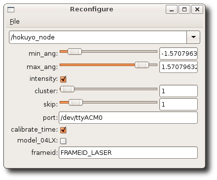
$ rosrun rqt_reconfigure rqt_reconfigure

now editable parameters be available:

11. 测试雷达数据
Running hokuyo_node
$ rosrun hokuyo_node hokuyo_node
— [ INFO] 1256687975.743438000: Connected to device with ID: H0807344

Viewing data
$ rosrun rviz rviz -d `rospack find hokuyo_node`/hokuyo_test.vcg

============================
Now, Hokuyo LiDAR LRF test tutorial:
==========================================

13. 初级方法

不通过在机器人模型urdf里面添加雷达模型joint/link,而是经由一个通过静态tf变换实现

13.1 准备一个加载driver的启动文件 – hokuyo_laser.launch

在turtlebot_navigation包之下建立启动文件 – hokuyo_laser.launch :
$ roscd turtlebot_navigation
$ mkdir -p laser/driver
复制这个启动文件:
$ sudo cp ~/turtlebot_ws/src/hokuyo_node/hokuyo_test.launch laser/driver/hokuyo_laser.launch
修改hokuyo_laser.launch
$ vi turtlebot_navigation hokuyo_laser.launch
* 检查框架frame_id是否指定为laser* 查看port是否指定正确端口,使用别名
检查端口:,设置好别名,或直接端口/dev/ttyACM0
* 增加TF变幻:

修改为args=”0.0 0.0 0.18 0 0.0 0.0 为自己的实际安装位置。详情查看: static_transform_publisher部分:
static_transform_publisher x y z qx qy qz qw frame_id child_frame_id period_in_ms
这里假设底盘的中心点为0,雷达放在机器人托盘中心位置,X为0,高度为18CM,Z为0.18m, TF的单位使用米的,测量单位是CM.

完整代码:

13.2 准备一个建图的配置文件 – hokuyo_gmapping.launch.xml

在turtlebot_navigation包之下建立配置文件 – hokuyo_gmapping.launch.xml:
$ roscd turtlebot_navigation
$ touch launch/includes/gmapping/hokuyo_gmapping.launch.xml
$ vi launch/includes/gmapping/hokuyo_gmapping.launch.xml

13.3 准备建图的启动文件 hokuyo_gmapping_demo.launch,在其中加载hokuyo_laser.launch驱动

在turtlebot_navigation包建立hokuyo_gmapping_demo.launch文件用于启动gmapping :
$ roscd turtlebot_navigation
$ touch launch/hokuyo_gmapping_demo.launch
这个touch命令不常用,一般在使用make时,用来修改时间戳,或新建一个不存在的文件。如果创建一个新文件有很多种方法,vi cat echo, 而touch命令不仅可以创建新文件,而且可以修改文件的时间属性。

$ vi launch/hokuyo_gmapping_demo.launch

NOTE: 设置laser_type为hokuyo_laser.launch.

13.4 测试激光雷达的gmapping建图

启动turtlebot
$ roslaunch turtlebot_bringup minimal.launch
启动gmapping,用于构建地图
$ roslaunch turtlebot_navigation hokuyo_gmapping_demo.launch
启动键盘操作Turtlebot
$ roslaunch turtlebot_teleop keyboard_teleop.launch
启动rviz,实时查看建图情况
$ roslaunch turtlebot_rviz_launchers view_navigation.launch
保存地图
$ rosrun map_server map_saver -f /tmp/hokuyo_gmapping

13.5 利用地图进行AMCL

15. 中级方法

使用机器人模型urdf, 直接在其中添加laser

15.1 add LiDAR to the robot model

Edit ./urdf/turtlebot_library.urdf.xacro and add the following right above the tag
$ vi ./urdf/turtlebot_library.urdf.xacro

Above files will have your kinect’s virutal laser scan publishing on the same topic that other tutorials want to use, but here we would rather the laser data would come from the hokuyo laser.
This can be prevented by changing the topic that the Kinect laser publishes on with the following.

15.3 edit 3dsensor to change kinect date on /scan_topic rather than /scan.

$ vi turtlebot_bringup/launch/3dsensor.launch
edit 3dsensor.launch and look for the line that looks like this:

Remove it and replace it with:

15.5 edit minimal.launch to add laser node

Then edit minimal.launch, for we now need to add the hokuyo node to it.
At the bottom of the file right before , add the following:

This should bring up the hokuyo node when you launch it.

15.7 Test config

Bringup new config:
$ roslaunch turtlebot_bringup minimal.launch
— process[laser_driver-9]: started with pid [8288]

In another terminal, you can bring up the kinect sensor by running:
$ roslaunch turtlebot_bringup 3dsensor.launch

Check your results with rviz.
Now run rviz. You should now have a block that appears on your turtlebot.
Add two LaserScan visuilizations.
Subscribe one of them to the /kinect_scan topic and set it’s Color to “2; 255; 255”
Subscribe the other topic to /scan. Leave it’s Color “255; 255; 255”

17. 高级方法

建立激光雷达的dae模型,然后加入机器人模型。

We should make the changes in Turtlebot URDF, Two things:
one is description about Hokuyo that is in meshes folder,
and the other is the defining join with its location and its relation with parent frame (joint).

17.1 Make the hokuyo.dae file
We copy the hokuyo.dae file from the driver into /opt/ros/indigo/share/turtlebot_description/meshes folder.
It need administrative and write privileges to do it .
These meshes file contain all the properties that are needed to define hokuyo_node.
$ sudo cp …../hokuyo.dae /opt/ros/indigo/share/turtlebot_description/meshes

17.2 Create a new Hokuyo URDF file – hokuyo.urdf.xacro
Create and edit the Hokuyo URDF file – hokuyo.urdf.xacro
First go the folder /opt/ros/indigo/share/turtlebot_description/urdf/sensors ,
then , create and edit a new file named hokuyo.urdf.xacro

$ sudo vi /opt/ros/indigo/share/turtlebot_description/urdf/sensors/hokuyo.urdf.xacro

The code focuses on two things:
the one is description about Hokuyo that is in meshes folder. hokuyo.dae,
the other is the defining join with its location and its relation with parent frame (joint).
link is laser_joint and joint is hokuyo_joint.

For finding the location of hokuyo sensor, you may need to calculate the location that will be in meters and the representation is in x,y,z .

Turtlebot assumes 0 0 0 at it base center, like blow.

Above Collision do provide the opportunity to take a decision before going to collide.
In above code we have defined collisions for more explanation look into Adding Collisions.
It is necessary to set the parameters to avoid collisions.

Above code, first thing we did is specifying the joint name that is Hokuyo (but can be changed to any other thing), the type we select as fixed then we defined where the Hokuyo is attached with respect to origin,
Next thing the joints are defined by parent and child, You can also specify some fixed frame like map or base_footprint or make it link to default parent

17.3 Add LiDAR to robot
Add Hokuyo URDF description – hokuyo.urdf.xacro to Turtlebot URDF description – turtlebot_library.urdf.xacro

In order to be Hokuyo a part of URDF description, we need to add Hokuyo LRF description to the Turtlebot URDF so that it can be visualized in rivz and other simulators.
So, edit /opt/ros/indigo/share/turtlebot_description/urdf/turtlebot_library.urdf.xacro file and add some lines:

$ sudo vi /opt/ros/indigo/share/turtlebot_description/urdf/turtlebot_library.urdf.xacro
add:

Above will call the hokuyo description created in urdf.

17.4 minimal.launch

In order to launch the description , it is just required to launch mininal.launch and it will work.
NOTE:
In order to see a hokuyo sensor in rviz we need to add its definition in gazebo, but not covered here,
but can be borrowed from Building Visual Robot:
http://wiki.ros.org/urdf/Tutorials/Building%20a%20Visual%20Robot%20Model%20with%20URDF%20from%20Scratch

17.5 Create Launch File for Hokuyo Node driver

Its is better to create a Hokuyo Launch file in order to launch the Hokuyo node.
It will also allow Hokuyo node dynamic re-configuration of Hokuyo node.

$ vi hokuyo.launch

正常做法是把这个驱动图的launch文件在minimal.launch中包含, 但是单独运行也没问题。

17.6 Use SLAM With Hokuyo LIDAR Sensor

利用hokuyo laser创建地图.
In order to use Hokuyo for SLAM as described in tutorial Building SLAM, following below:

地图:
a)
$ roslaunch turtlebot_bringup minimal.launch
b) run the Hokuyo node
$ roslaunch turtlebot_test_launch hokuyo.launch

c) Launch the gmapping for map building
$ roslaunch turtlebot_navigation gmapping_demo.launch

d) View the map at workstation using rviz
$ roslaunch turtlebot_rviz_launchers view_navigation.launch
e)
$ roslaunch turtlebot_teleop keyboard_teleop.launch
f) 地图构建完成之后保存 :
$ rosrun map_server map_saver -f /tmp/my_map

导航:
a)
$ roslaunch turtlebot_navigation amcl_demo.launch map_file:=/tmp/my_map.ymal
b)
$ roslaunch turtlebot_rviz_launchers view_navigation.launch
c) 2D Pose Estimate
d) 2D Nav Goal

Available for UTM-30LX,UBG-04LX-F01, URG-04LX, URG-04LX-UG01, UTM-04G…
REF:
http://www.iroboapp.org/index.php?title=Adding_Hokuyo_Laser_Range_Finder_to_Turtlebot
http://www.voidcn.com/blog/jie_sky_2015/article/p-5698136.html
http://wiki.ros.org/turtlebot/Tutorials/hydro/Adding%20a%20Hokuyo%20laser%20to%20your%20Turtlebot
http://www.ncnynl.com/archives/201611/1097.html
http://amanbreakingthings.blogspot.hk/2014/11/adding-hokuyo-lidar-to-turtlebot-in-ros.html
http://www.iheartrobotics.com/2012/03/in-stock-even-more-turtlebot.html
http://blog.sina.com.cn/s/blog_c5a00db10102wg07.html

智能机器人(18):人工智能

人工智能AI,可以简单用模式匹配和全文检索来实现,前面说的爱丽丝Alice比较简洁,它有多种语言实现:programD是Java版本,programE是PHP版本,programQ是Cpp版本,programV是Perl,programY是Python等等,作网站应用Java和PHP不错,做智能终端C++和Python不错。

  • 1、语言选择

既然论及人工智能AI,使用 C/C++就有点不合时宜,这需要感谢肉丝ROS的语言独立性,从而可以用C作机器人的底盘控制,用C++作机器人视觉导航,用Python作机器人的人工智能,混搭,挺好。选择python还有考虑是这个program-Y版本是纯粹用python实现的,不依赖于第三方。不像C++版本的 programD还要依赖与Qt的库,比较干净一些。

Alice的Python版叫pyAIML,这个术语,如果颗粒度小一些:前面的py表示是python脚本语言实现的,中间的ai表明说用于人工智能的xml,最后的ml表示这是标记语言,标志语言常见的有xml和yaml;如果颗粒度大些:前面的py表明前端的解释器用pytthon实现,后面的aiml表明模式匹配使用标记语言实现。

  • 2、大体结构

ALICE主要包括三块内容:programx内核、AIML标记语言、解释器接口。Kernel核心有源代码,解释器接口主要是Mysql数据库导入aiml文件。复杂些的是AIML,也就是XML,扩展标记语言。

AIML主要用来实现模式匹配,pattern matching。在好多文献里,例如半导体行业计算机视觉行业等等,都会提到pattern这个词不好翻译。感觉就是规律,例如一个人总是七点二十出门六点四十回家,这个就是强模式。再比如一个人走路总是向左侧着身子,那么也就具有了模式性,好像这个可以用于刑事侦查。再比如种植行业怎么分拣梨子和苹果,圆度,这个也是用模式匹配。至于具有模式性是好事坏,很难讲,模式太强说明熵比较大,也不算是好事。自然界本来是浑沌的,现在弄的铁是铁硅是硅山是山水是水,熵一增大就不稳定了,看来三峡大坝不怎么好。
回到Alice,在它的后缀.aiml文件(有时也用.xml)里,常见标签有category,主要包含输入模式pattern和响应模板template两个节。

  • 3、AIML安装

首先确保python正确
$ python -V
检查源
$ sudo gedit /etc/apt/sources.list
需要的话修改
$ deb http://us.archive.ubuntu.com/ubuntu precise main universe
更新
$ sudo apt-get update
安装软件
$ sudo apt-get install python-aiml
测试,如果正确导入则安装okay
$ python
>>>import aiml #导入
如果未提示异常说明安装正确。

  • 4、HelloWorld

1、一般流程
AIML最重要的一个类是Kernel(),用来学习AIML数据文件,并从AIML数据集获取用户响应,常规流程是:
myBot = aiml.Kernel() #建立Kernel类的对象实例
mybot.setBotPredicate(“name”,”myBot”) #给机器人命名
mybot.learn(‘myaiml.aiml’) #学习一个或多个AIML文件(载入内存)
//mybot.learn(“myStartup.xml”) #如果导入多个文件用这种xml的方法
mybot.respond(” load aiml b”) #触发myStartup.xml中的load aiml b模式
while True: print k.respond( raw_input(“> “)) #通过命令行接口CLI的方式交互用户

2、建个最简单的hello.aiml,中英文混搭,注意要大写
<aiml version =”1.0.1″ encoding =”UTF-8”>
<category>
<pattern>你好</pattern>
<template>不错</template>
</category>
<category>
<pattern>天</pattern>
<template>地</template>
</category>
<category>
<pattern>HOW ARE YOU</pattern>
<template>I am fine</template>
</category>
</aiml>

3、建立这个最简单的脚本hello.py,注意Python2和3的版本区别,以及unicode和UTF-8的区别

#!/usr/bin/env python
# -*- coding: utf-8 -*-
import aiml
import sys
mybot = aiml.Kernel()
mybot.learn(sys.argv[1])
while True:
print mybot.respond( raw_input(‘访客说: ‘)), ‘n’

4、给脚本加上可执行,测试
$ chmod + x hello.py
$ ./hello.py hello.aiml
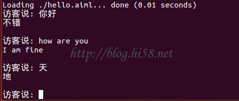
对话如下:

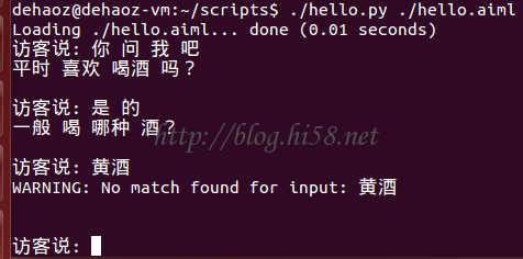
当访客输入“天”的时候,mybot检索数据库,给出“地”的回答,这个很简单。然而就在如此简单的结构上,加入诸多辅助标签,就可以理解复杂难懂的问题。

  • 5、其他标签

1、在aiml文件加入以下内容,试验<that>辅助标签作用
<category>
<pattern>你 问 我 吧</pattern>
<template>平时 喜欢 喝酒 吗?</template>
</category>
<category>
<pattern>是 的</pattern>
<that>平时 喜欢 喝酒 吗?</that>
<template>一般 喝 哪种 酒?</template>
</category>
<category>
<pattern>是 的</pattern>
<that>平时 喜欢 喝茶 吗?</that>
<template>一般 喝 哪种 茶?</template>
</category>

对话如下:

从上面aiml可以看出,that就是上句的意思,也就是访客说是的,后台可以匹配出一大堆的pattern/template对,在上面的例子里面至少有A和B两条,访客都是回答是的,那么机器人具体要用哪个,得看上一句。

2、再例如在aiml文件加入以下内容,试验<srai>这个辅助标签:

<category>
<pattern>下雪 了</pattern>
<template>真 好 啊</template>
</category>
<category>
<pattern>有 啥 好 的</pattern>
<that>真 好 啊</that>
<template>
<srai>好 个 大头 鬼</srai>
</template>
</category>
<category>
<pattern>好 个 大头 鬼</pattern>
<template>呵呵,瑞雪 兆 丰年 么 </template>
</category>

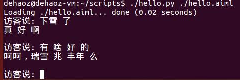
对话如下:

通过上一句的真好啊,后台匹配到A,而A却并没有明确给出结果只是提供了一个srai,说明理解尚未结束匹配还得继续,于是后台继续检索数据库终于从B的pattern/template对匹配到呵呵瑞雪兆丰年,最终输出。