机器人操作系统ROS(23):urdf模型
INDEX
1. pre-required urdf_tutorial package
1.1 About joint_state_publisher package
1.2 About pr2_description package
3. Building a Visual Robot Model from Scratch
3.1 only one simple shape by link
3.2 Multiple Shapes links by fixed-joint
3.3 Set Origins by origin
3.4 urdf with Material Girl
3.5 Finishing
5. Building a Movable Robot Model
5.1 Head
5.2 Gripper
5.3 Gripper Arm
5.4 Other Types of Joints
5.5 Specifying the Pose
7. Adding Physical and Collision Properties
7.1 Collision
7.2 Physical Properties
9. xacro Package
9.1 Property and Property Blocks
9.2 Math expressions
9.3 Conditional Blocks
9.4 Rospack commands
9.5 Macros
9.7 Including other xacro files
9.8 YAML support
11. Using Xacro to Clean Up a URDF File
11.1 Using Xacro
11.2 Constants
11.3 Math
11.4 Macros
11.5 Practical Usage
13. Understanding the PR2 Robot Description
15. Create your own urdf file
15.1 Create the tree structure
15.2 Add the dimensions
15.3 Completing the Kinematics
17. Parse a urdf file
19. Using the robot state publisher on your own robot
21. Using urdf with robot_state_publisher
21.1 Create the URDF File
21.2 Publishing the State
21.3 Launch File
21.4 Viewing the Results
23. Using a URDF in Gazebo
23.1 Background
23.2 Converting to Gazebo
23.3 The Element
23.4 Prerequisites
23.5 Header of a URDF File
23.6 Fixing A Model to the World
23.7 example link from RRBot
23.8 STL and Collada files
23.9 Verifying the Gazebo Model Works
25 Using Gazebo plugins with ROS
27 ROS Control
29 err
APP:
A1. TOOLS
A. urdf-XML-sensor
( URDF需要先了解:wiki.ros.org/urdf/Tutorials. )
1. pre-required of urdf_tutorial package
we’re going to build a visual model of a robot that vaguely looks like R2D2 and make it move in Gazebo. Before continuing, make sure you have the joint_state_publisher and pr2_description packages by installing urdf_tutorial.
$ sudo apt-get install ros-indigo-urdf-tutorial
1.1 About joint_state_publisher package
This package publishes sensor_msgs/JointState messages for a robot.
The package reads the robot_description parameter, finds all of the non-fixed joints and publishes a JointState message with all those joints defined.
Can be used in conjunction with the robot_state_publisher node to also publish transforms for all joint states.
—— sensor_msgs/JointState Message Definition
# This is a message that holds data to describe the state of a set of torque controlled joints.
# The state of each joint (revolute or prismatic) is defined by:
# * the position of the joint (rad or m),
# * the velocity of the joint (rad/s or m/s) and
# * the effort that is applied in the joint (Nm or N).
# Each joint is uniquely identified by its name
# The header specifies the time at which the joint states were recorded.
std_msgs/Header header
string[] name
float64[] position
float64[] velocity
float64[] effort
——> input
About data input, There are possible four sources for the value of each JointState:
* Values directly input through the GUI
* JointState messages that the node subscribes to
* The value of another joint
* The default value
output ——>
Published Topics: joint_states
Parameters: robot_description (String, default: None), Contents of the URDF file for the robot
—— parameters
robot_description :
Contents of the URDF file for the robot.
Dependent Joints:
Can specified through the dependent_joints parameter or the mimic tag in the URDF to lets you constrain certain joints to be equal to other joints, or multiples of other joints.
Default value:
The default value is zero. If zero is not a permissible value (max+min)/2 is used. To override the default value for some joints, use the zeros parameter.
—— Example YAML file:
Examples of how to set the dependent_joints and the zeros parameters using YAML syntax.
dependent_joints:
joint_D: {parent: joint_A, factor: 3 }
joint_E: {parent: joint_B }
joint_F: {parent: joint_C, factor: -1 }
zeros:
joint_A: 1.57
joint_B: 0.785

1.2 About pr2_description package
This package contains the description (mechanical, kinematic, visual, etc.) of the PR2 robot. The files in this package are parsed and used by a variety of other components. Most users will not interact directly with this package.
—— pr2_description organized subdirectories:
* urdf/ ,contains (xacro representations of) urdf descriptions of various parts of the PR2 (arm, torso, etc.).
* robots/ ,contains (xacro representations of) urdf descriptions of the full robot, that refer to the macros in urdf
* gazebo/ ,contains (xacro representations of) urdf descriptions of simulated PR2 components, like the simulated battery controller.
* meshes/ , contains mesh files (.stl,.dae) for visualization and collision properties.
To see the PR2 URDF graphically:
$ rosrun xacro xacro.py `rospack find pr2_description`/robots/pr2.urdf.xacro > pr2.urdf
$ rosrun urdf urdf_to_graphiz pr2.urdf
$ evince pr2.pdf
To use the original Kinect with the PR2 (either robot or simulation), set the KINECT1 environment variable to true.
export KINECT1=true
To use a Kinect2 with the PR2 (either robot or simulation), set the KINECT2 environment variable to true.
export KINECT2=true
If both variables are set, the Kinect 2 will take precedence over the original Kinect.
3. Building a Visual Robot Model from Scratch
Learn how to build a visual model of a robot looks like R2D2 that you can view in Rviz
3.1 only one simple shape by link
this is a robot with the name myfirst, that contains only one link (a.k.a. part), whose visual component is just a cylinder .6 meters long with a .2 meter radius.
To examine the model by launch the display.launch file:
$ roslaunch urdf_tutorial display.launch model:=urdf/01-myfirst.urdf
or,
$ roslaunch urdf_tutorial display.launch model:=’$(find urdf_tutorial)/urdf/01-myfirst.urdf’
Note that the roslaunch line above does three things:
* Loads the specified model into the parameter server
* Runs nodes to publish sensor_msgs/JointState and transforms
* Starts Rviz with a configuration file
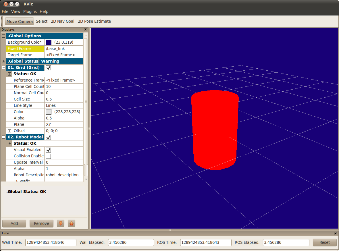
NOTE:
* The fixed frame is transform frame where the center of the grid is located. Here, it’s a frame defined by our one link, base_link.
* The visual element (the cylinder) has its origin at the center of its geometry as a default. Hence, half the cylinder is below the grid.
3.2 Multiple Shapes links by fixed-joint
Lets look at how to add multiple shapes/links.
If we just add more link elements to the urdf, the parser won’t know where to put them. So, we have to add joints. Joint elements can refer to both flexible and inflexible joints.
We’ll start with inflexible, or named fixed joints.
$ roslaunch urdf_tutorial display.launch model:=urdf/02-multipleshapes.urdf
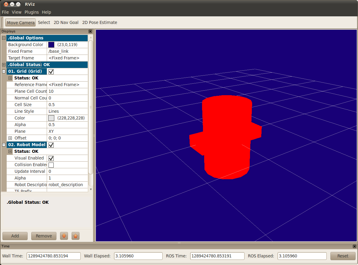
x+ axis direction is 0.6, y+ is 0.2 width, and z+ is 0.1 deepth.
But Both of the shapes overlap with each other, because they share the same origin. If we want them not to overlap we must define more origins–>
3.3 Set Origins by origin
So R2D2’s leg attaches to the top half of his body, on the side where we specify the origin of the JOINT to be. Also, it doesn’t attach to the middle of the leg, it attaches to the upper part, so we must offset the origin for the leg as well. We also rotate the leg so it is upright.
* The joint’s origin is defined in terms of the parent’s reference frame, ‘joint — origin xyz=”0.22 0 .25’, we are .22 meters in the x direction (left) and .25 meters in the z direction (up). This means that the origin for the child link will be up and to the left, regardless of the child link’s visual origin tag. Since we didn’t specify a rpy (roll pitch yaw) attribute, the child frame will be default have the same orientation as the parent frame.
* The leg’s visual origin, origin rpy=”0 1.57075 0″ xyz=”0 0 -0.3″, has both a xyz and rpy offset. This defines where the center of the visual element should be, relative to its origin. Since we want the leg to attach at the top, we offset the origin down by setting the z offset to be -.3 meters. And since we want the long part of the leg to be parallel to the z axis, we rotate the visual part PI/2 around the Y axis.
$ roslaunch urdf_tutorial display.launch model:=urdf/03-origins.urdf
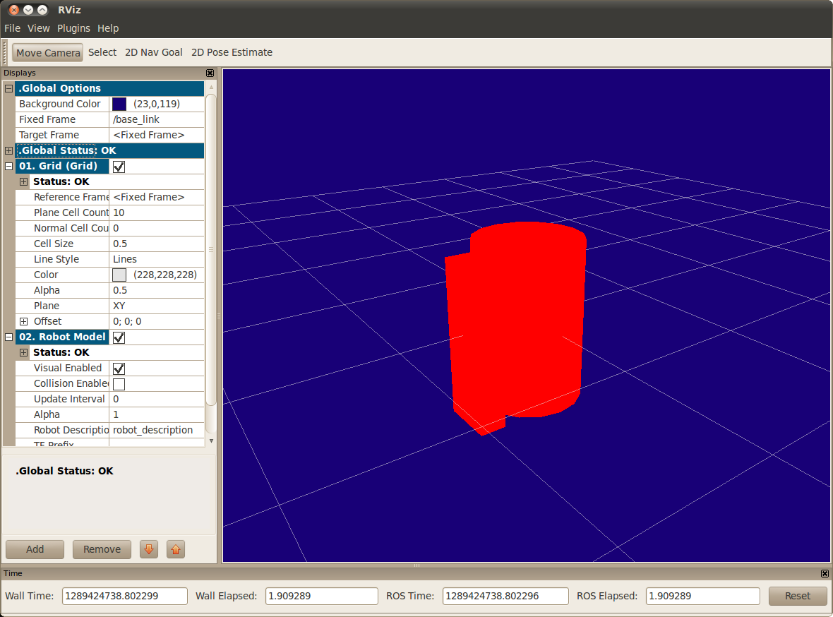
The launch file runs packages that will create TF frames for each link in your model based on your URDF. Rviz uses this information to figure out where to display each shape.
3.4 urdf with Material Girl
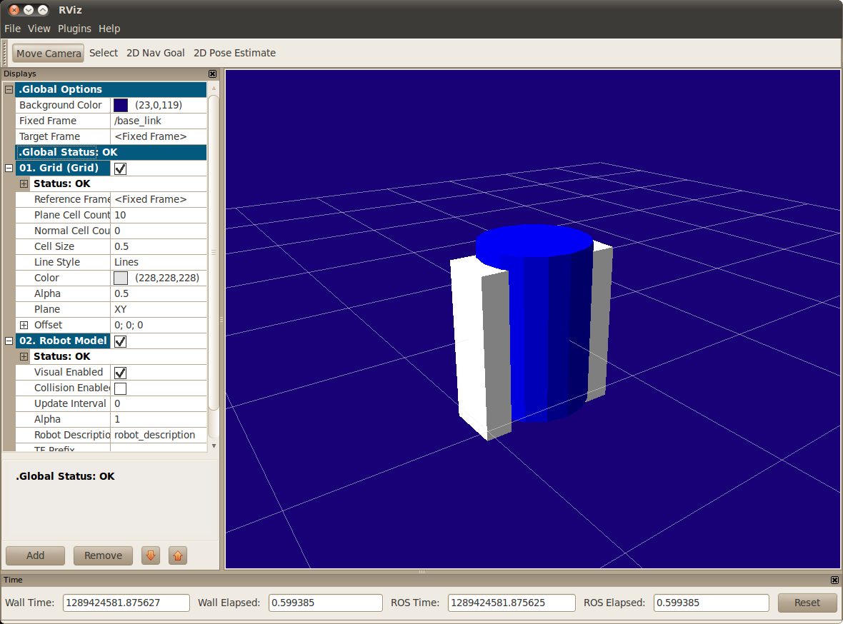
Color? My robot are not red? Let’s take a look at the material tag:
$ roslaunch urdf_tutorial display.launch model:=urdf/04-materials.urdf
3.5 Finishing
Now we finish with a few more shapes. Most notably, we add a sphere and a some meshes. We’ll also add few other pieces that we’ll use later.
$ roslaunch urdf_tutorial display.launch model:=urdf/05-visual.urdf
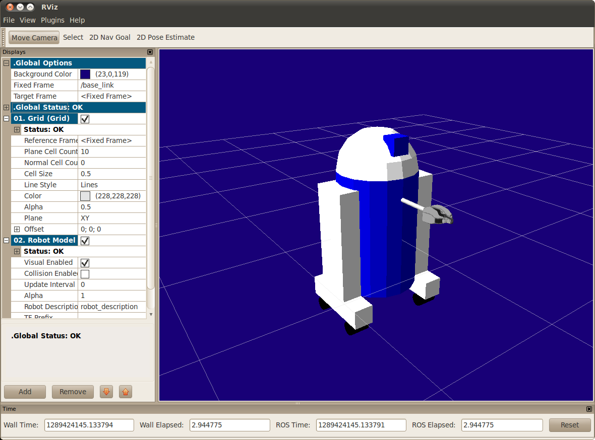
About codes to add the sphere
Above The meshes were borrowed from the PR2, meaning you’ll need the package pr2_description to be able to see them.
* The meshes can be imported in a number of different formats. STL is fairly common, but the engine also supports DAE, which can have its own color data, meaning you don’t have to specify the color data.
* Meshes can also be sized using relative scaling parameters or a bounding box size.
Ok we have a R2D2-like URDF model now,
next step, make it mve.
5. Building a Movable Robot Model
In the previous model, all of the joints were fixed.
Now we’ll explore three other important types of joints: continuous连续, revolute旋转,prismatic棱形副。
URDF source here:
$ roslaunch urdf_tutorial display.launch model:=urdf/06-flexible.urdf gui:=True
This will visualize and control this model also pop up a GUI that allows you to control the values of all the non-fixed joints.
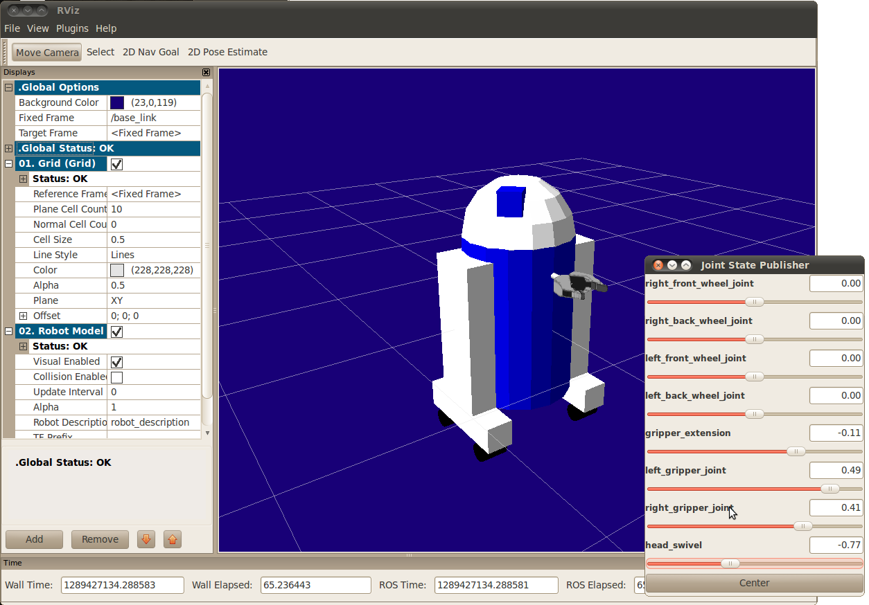
Now focus on three example joints.
5.1 Head
swivel旋转关节,The connection between the body and the head is a continuous joint, meaning that it can take on any angle from negative infinity to positive infinity. The wheels are also modeled like this, so that they can roll in both directions forever.
The only additional information we have to add is the axis of rotation, here specified by an xyz which specifies a vector around which the head will rotate. Since we want it to go around the z axis, we specify the vector “0 0 1”.
5.2 Gripper
Both the right and the left gripper joints are modeled as revolute joints. revolute joints means that they rotate in the same way that the continuous joints do, but they have strict limits. Hence, we must include the limit tag specifying the upper and lower limits of the joint (in radians). We also must specify a maximum velocity and effort for this joint. You can also specify the maximum effort and velocity for continuous joints but you don’t have to.
5.3 Gripper Arm
The gripper arm is a different kind of joint…namely a prismatic joint. This means that it moves along an axis, not around it. This translational movement is what allows our robot model to forwared-extend and backword-retract its gripper arm.
The limits of the prismatic arm are specified in the same way as a revolute joint, except that the units are meters, not radians.
5.4 Other Types of Joints
There are two other kinds of joints that move around in space. Whereas the prismatic joint can only move along one dimension, a planar joint can move around in a plane, or two dimensions. Furthermore, a floating joint is unconstrained, and can move around in any of the three dimensions.
5.5 Specifying the Pose
As you move the sliders around in the GUI, the model moves in Rviz. How is this done?
First the GUI parses the URDF and finds all the non-fixed joints and their limits. Then, it uses the values of the sliders to publish sensor_msgs/JointState messages.
Those are then used by robot_state_publisher to calculate all of transforms between the different parts. The resulting transform tree is then used to display all of the shapes in Rviz.
7. Adding Physical and Collision Properties
7.1 Collision
So far, we’ve only specified our links with a single sub-element, visual, which defines (not surprisingly) what the robot looks like. However, in order to get collision detection to work or to simulate the robot in something like Gazebo, we need to define a collision element as well.
URDF source:
Code for our new base link:
* The collision element is a direct subelement of the link object, at the same level as the visual tag
* The collision element defines its shape the same way the visual element does, with a geometry tag.
* You can also specify an origin in the same way as a subelement of the collision tag (as with the visual)
In many cases, you’ll want the collision geometry and origin to be exactly the same as the visual geometry and origin. However, there are two main cases where you wouldn’t:
* Quicker Processing – Doing collision detection for two meshes is a lot more computational complex than for two simple geometries. Hence, you may want to replace the meshes with simpler geometries in the collision element.
* Safe Zones – You may want to restrict movement close to sensitive equipment. For instance, if we didn’t want anything to collide with R2D2’s head, we might define the collision geometry to be a cylinder encasing his head to prevent anything from getting to near his head.
7.2 Physical Properties
In order to get your model to simulate properly, you need to define several physical properties of your robot, i.e. the properties that a physics engine like Gazebo would need.
7.2.1 Inertia 惯性
Every link element being simulated needs an inertial tag:
* This element is also a subelement of the link object.
* The mass is defined in kilograms.
* The 3×3 rotational inertia matrix is specified with the inertia element. Since this is symmetrical, it can be represented by only 6 elements, as such.
ixx/ixy/ixz,ixy/iyy/iyz,ixz/iyz/izz
* This information can be provided to you by modeling programs such as MeshLab.
* The inertia tensor depends on both the mass and the distribution of mass of the object. A good first approximation is to assume equal distribution of mass in the volume of the object and compute the inertia tensor based on the object’s shape, as outlined above.
* If unsure what to put, a matrix with ixx/iyy/izz=1e-3 or smaller is often a reasonable default for a mid-sized link (it corresponds to a box of 0.1 m side length with a mass of 0.6 kg). Although often chosen, the identity matrix is a particularly bad default, since it is often much too high (it corresponds to a box of 0.1 m side length with a mass of 600 kg!).
* You can also specify an origin tag to specify the center of gravity and the inertial reference frame (relative to the link’s reference frame).
* When using realtime controllers, inertia elements of zero (or almost zero) can cause the robot model to collapse without warning, and all links will appear with their origins coinciding with the world origin.
7.2.2 Contact Coefficients
You can also define how the links behave when they are in contact with one another. This is done with a subelement of the collision tag called contact_coefficients. There are three attributes to specify:
mu – The friction coefficient
kp – Stiffness coefficient
kd – Dampening coefficient
7.2.3 Joint Dynamics
How the joint moves is defined by the dynamics tag for the joint. There are two attributes here:
friction – The physical static friction. For prismatic joints, the units are Newtons. For revolving joints, the units are Newton meters.
damping – The physical damping value. For prismatic joints, the units are Newton seconds per meter. For revolving joints, Newton meter secons per radian.
7.2.4 Other Tags
In the realm of pure URDF (i.e. excluding Gazebo-specific tags), there are two remaining tags to help define the joints: calibration and safety controller.
9. xacro Package
xacro is a macro language. xacro package is most useful when working with large XML documents such as robot descriptions.
Consider the following Xacro XML example:
Above code expands to: If we also define macros for pr2_upperarm and pr2_forearm, then this snippet could expand to describe an entire robotic arm.
9.1 Property and Property Blocks
Properties are named values that can be inserted anywhere into the XML document. Property blocks are named snippets of XML that can be inserted anywhere that XML is allowed. Both use the property tag to define values. Property tags cannot be declared inside of a xacro:macro. The following example shows how to declare and use a property:
The two properties are inserted into the geometry expression by placing the names inside dollared-braces (${}). If you want a literal “${“, you should escape it as “$${“.
Here’s an example of using a property block:
9.2 Math expressions
Within dollared-braces (${}), you can also write simple math expressions. Currently, basic arithmetic and variable substitution is supported. Here’s an example:
9.3 Conditional Blocks
9.4 Rospack commands
Xacro allows you to use certain rospack commands with dollared-parentheses ($()).
Since ROS Indigo, it is also possible to define defaults like so:
Using this you can run xacro like:
9.5 Macros
The main feature of xacro is its support for macros. Define macros with the macro tag, and specify the macro name and the list of parameters. The list of parameters should be whitespace separated. They become macro-local properties.
9.7 Including other xacro files
You can include other xacro files using the xacro:include tag:
To avoid name clashes between properties and macros of various included files, you can specify a namespace for the included file – providing the attribute ns:
9.8 YAML support
11. Using Xacro to Clean Up a URDF File
you might be sick of doing all sorts of math to get very simple robot descriptions to parse correctly. you can use the xacro package to make your life simpler. It’s easy to do three things that are very helpful.
* Constants
* Simple Math
* Macros
Here take a look at all these shortcuts to help reduce the overall size of the URDF file and make it easier to read and maintain. It is heavily used in packages such as the urdf.
11.1 Using Xacro
The xacro program runs all of the macros and outputs the result. Typical usage looks something like this:
$ rosrun xacro xacro model.xacro > model.urdf
You can also automatically generate the urdf in a launch file. This is convenient because it stays up to date and doesn’t use up hard drive space. However, it does take time to generate, so be aware that your launch file might take longer to start up.
You must specify a namespace in order for the file to parse properly. For example, these are the first two lines of a valid xacro file:
11.2 Constants
Let’s take a quick look at our base_link in R2D2.
The information here is a little redundant. We specify the length and radius of the cylinder twice. Worse, if we want to change that, we need to do so in two different places.
Fortunately, xacro allows you to specify properties which act as constants. Instead, of the above code, we can write this.
* The two values are specified in the first two lines. They can be defined just about anywhere (assuming valid XML), at any level, before or after they are used. Usually they go at the top.
* Instead of specifying the actual radius in the geometry element, we use a dollar sign and curly brackets to signify the value.
* This code will generate the same code shown above.
The value of the contents of the ${} construct are then used to replace the ${}. This means you can combine it with other text in the attribute.
This will generate
However, the contents in the ${} don’t have to only be a property, which brings us to next point…
11.3 Math
You can build up arbitrarily complex expressions in the ${} construct using the four basic operations (+,-,*,/), the unary minus, and parenthesis. Exponentiation and modulus are not supported. Examples:
11.4 Macros
Here’s the biggest and most useful component to the xacro package.
11.4.1 Simple Macro
Let’s take a look at a simple useless macro.
This code will generate the following.
* The name is not technically a required element, but you need to specify it to be able to use it.
* Every instance of the <xacro:$name> is replaced with the contents of the xacro:macro tag.
* !!! If the xacro with a specified name is not found, it will not be expanded and will NOT generate an error. </xacro:$name>
11.4.2 Parameterized Macro
You can also parameterize macros so that they don’t generate the same exact text every time. When combined with the math functionality, this is even more powerful. First, let’s take an example of a simple macro used in R2D2.
This can be used with the code
The parameters act just like properties, and you can use them in expressions
11.5 Practical Usage
The xacro language is rather flexible in what it allows you to do. Here are a few useful ways that the xacro is used in the R2D2 model, in addition to the default inertial macro shown above:
To see the model generated by a xacro file, run this command:
$ roslaunch urdf_tutorial xacrodisplay.launch model:=urdf/08-macroed.urdf.xacro
11.5.1 Leg macro
Often you want to create multiple similar looking objects in different locations. Often, there will be some symmetry to the locations. You can use a macro and some simple math to reduce the amount of code you have to write, like we do with R2’s two legs.
* Use a name prefix to get two similarly named objects
* Use math to calculate joint origins.
* Using a reflect parameter, and setting it to 1 or -1.
13. Understanding the PR2 Robot Description
Now refers to the description in pr2_defs, which has now been replaced by the one in pr2_description.
In particular, the XML schemas specified in the element are no longer required by Gazebo, and all references to Gazebo plugins are incorrect as their API has changed considerably. Now let’s break down the entire XML piece by piece
The root element for the XML must be robot with a name attribute. XML namespaces are declared here.
Include files containing xacro macros for inidividual robot components. This is like including a header file in C: it sets up a bunch of definitions but doesn’t actually call any of them.
Some useful comments
we actually use the macros defined above. Here, we define PR2’s base, using the xacro:pr2_base_v0 macro, with name parameter equal to “base” and an origin parameter block. After running the original file through the xacro preprocessor, this element will be replaced with a rather long URDF definition of the base and its components.
Similarly, we define the PR2 torso, using the xacro:pr2_torso_v0 macro, which can be found in the included file pr2_description/urdf/torso_v0/torso.urdf.xacro.
PR2 head sensor packages, including two interlacing stereo cameras and a high resolution Prosilica GC2450 camera.
PR2 tilting Hokuyo laser range scanner.
15. Create your own urdf file
15.1 Create the tree structure
Now start creating your own urdf robot description file. we’ll create the URDF description of the “robot” shown in the image below.
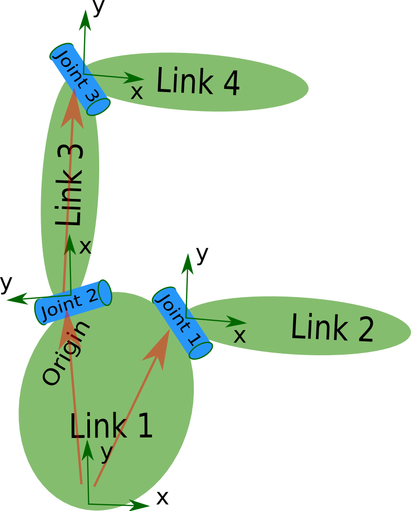
The robot in the image is a tree structure. Let’s start very simple, and create a description of that tree structure, without worrying about the dimensions etc.
Create a file called my_robot.urdf:
So, just creating the structure is very simple! Now let’s see if we can get this urdf file parsed. There is a simple command line tool that will parse a urdf file for you, and tell you if the syntax is correct.
First, You might need to install, urdfdom as an upstream, ROS independent package:
$ sudo apt-get install liburdfdom-tools
Then run the check command
$ rosrun urdf check_urdf my_robot.urdf # older versions
$ rosrun urdf_parser check_urdf my_robot.urdf # electric and fuerte
$ rosrun urdfdom check_urdf my_robot.urdf # groovy
$ check_urdf my_robot.urdf # hydro onward
———
robot name is: test_robot
———- Successfully Parsed XML —————
root Link: link1 has 2 child(ren)
child(1): link2
child(2): link3
child(1): link4
15.2 Add the dimensions
So now that we have the basic tree structure, let’s add the appropriate dimensions. As you notice in the robot image, the reference frame of each link (in green) is located at the bottom of the link, and is identical to the reference frame of the joint. So, to add dimensions to our tree, all we have to specify is the offset from a link to the joint(s) of its children. To accomplish this, we will add the field to each of the joints.
Let’s look at the second joint Joint2.
Joint2 is offset in the Y-direction from link1,
a little offset in the negative X-direction from link1,
and it is rotated 90 degrees around the Z-axis. So, we need to add the following element:
If you repeat this for all the elements our URDF will look like this:
Update your file my_robot.urdf and run it through the parser:
$ check_urdf my_robot.urdf
15.3 Completing the Kinematics
What we didn’t specify yet is around which axis the joints rotate. Once we add that, we actually have a full kinematic model of this robot! All we need to do is add the element to each joint. The axis specifies the rotational axis in the local frame.
So, if you look at joint2, you see it rotates around the positive Y-axis. So, simple add the following xml to the joint element:
Similarly, joint1 is rotating around the following axis:
Note that it is a good idea to normalize the axis.
If we add this to all the joints of the robot, our URDF looks like this:
Update your file my_robot.urdf and run it through the parser:
$ check_urdf my_robot.urdf
That’s it, you created your first URDF robot description! Now you can try to visualize the URDF using graphiz:
$ urdf_to_graphiz my_robot.urdf
$ evince test_robot.pdf
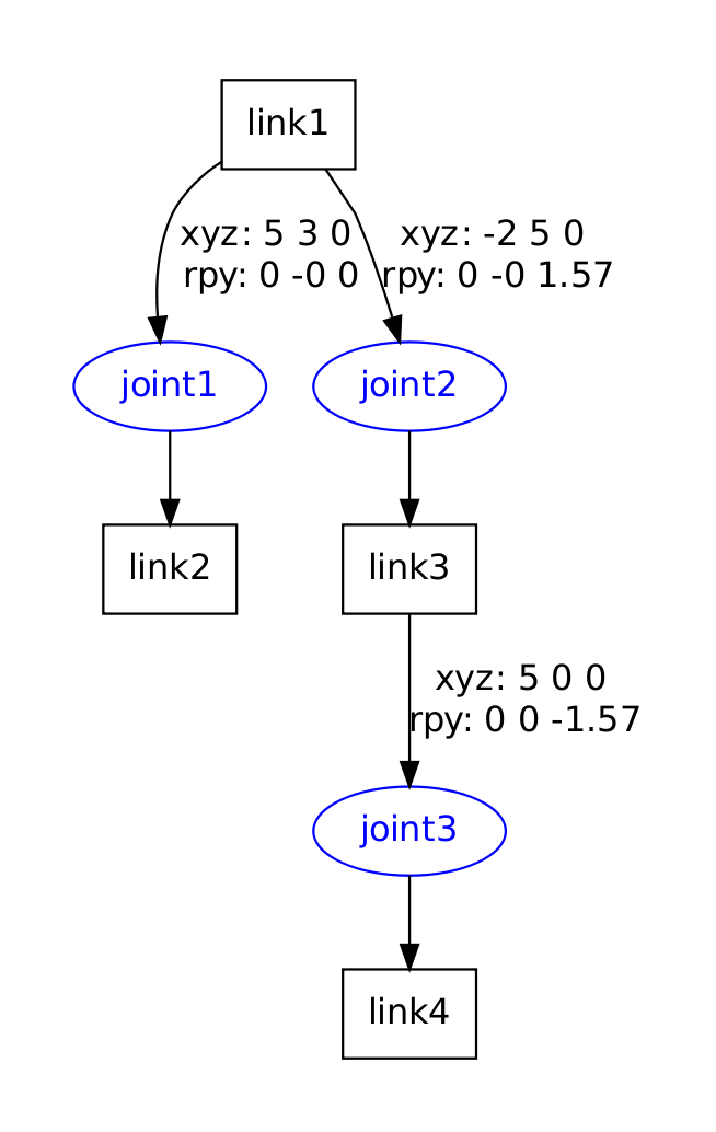
17. Parse a urdf file
with the same my_robot.urdf file description of the robot shown above.
first create a package with a dependency on the urdf parser in our sandbox:
$ cd ~/catkin_ws/src
$ catkin_create_pkg testbot_description urdf
$ cd testbot_description
Now create a /urdf folder to store the urdf file we just created:
$ mkdir urdf
$ cd urdf
This follows the convention of always storing your robot’s URDF file in a ROS package named MYROBOT_description and within a subfolder named /urdf.
Other standard subfolders of your robot’s description package include /meshes, /media and /cad, like so:
/MYROBOT_description
package.xml
CMakeLists.txt
/urdf
/meshes
/materials
/cad
Next, copy your my_robot.urdf file to the package and folder we just created:
$ cp /path/to/…/testbot_description/urdf/my_robot.urdf .
Create a folder src/ and create a file called src/parser.cpp:
#include
#include “ros/ros.h”
int main(int argc, char** argv){
ros::init(argc, argv, “my_parser”);
if (argc != 2){
ROS_ERROR(“Need a urdf file as argument”);
return -1;
}
std::string urdf_file = argv[1];
urdf::Model model;
if (!model.initFile(urdf_file)){
ROS_ERROR(“Failed to parse urdf file”);
return -1;
}
ROS_INFO(“Successfully parsed urdf file”);
return 0;
}
urdf::Model is a class containing robot model data structure.
Every Robot Description File (URDF) can be described as a list of Links (urdf::Model::links_) and Joints (urdf::Model::joints_).
The connection between links(nodes) and joints(edges) should define a tree (i.e. 1 parent link, 0+ children links).
try to run this code.
First add the following lines to your CMakeList.txt file:
add_executable(parser src/parser.cpp)
target_link_libraries(parser ${catkin_LIBRARIES})
build your package,
$ cd ~/catkin_ws
$ catkin_make
and run it.
$ ./parser my_robot.urdf
— [ INFO] 1254520129.560927000: Successfully parsed urdf file
A good example of the URDF model class in action is rviz’s Robot::load
19. Using the robot state publisher on your own robot
you can publish the state of your robot to tf, using the robot state publisher.
Example launch file
21. Using urdf with robot_state_publisher
A full example of a robot model with URDF that uses robot_state_publisher.
First, we create the URDF model with all the necessary parts. Then we write a node which publishes the JointState and transforms. Finally, we run all the parts together.
21.1 Create the URDF File
Here is the URDF file for a 7-link model roughly approximating R2-D2.
21.2 Publishing the State
Now we need a method for specifying what state the robot is in. To do this, we must specify all three joints and the overall odometry. Start by creating a package:
$ cd %TOP_DIR_YOUR_CATKIN_WS%/src
$ catkin_create_pkg r2d2 roscpp rospy tf sensor_msgs std_msgs
then create src/state_publisher.cpp file:
#include
#include
#include
#include
int main(int argc, char** argv) {
ros::init(argc, argv, “state_publisher”);
ros::NodeHandle n;
ros::Publisher joint_pub = n.advertise(“joint_states”, 1);
tf::TransformBroadcaster broadcaster;
ros::Rate loop_rate(30);
const double degree = M_PI/180;
// robot state
double tilt = 0, tinc = degree, swivel=0, angle=0, height=0, hinc=0.005;
// message declarations
geometry_msgs::TransformStamped odom_trans;
sensor_msgs::JointState joint_state;
odom_trans.header.frame_id = “odom”;
odom_trans.child_frame_id = “axis”;
while (ros::ok()) {
//update joint_state
joint_state.header.stamp = ros::Time::now();
joint_state.name.resize(3);
joint_state.position.resize(3);
joint_state.name[0] =”swivel”;
joint_state.position[0] = swivel;
joint_state.name[1] =”tilt”;
joint_state.position[1] = tilt;
joint_state.name[2] =”periscope”;
joint_state.position[2] = height;
// update transform
// (moving in a circle with radius=2)
odom_trans.header.stamp = ros::Time::now();
odom_trans.transform.translation.x = cos(angle)*2;
odom_trans.transform.translation.y = sin(angle)*2;
odom_trans.transform.translation.z = .7;
odom_trans.transform.rotation = tf::createQuaternionMsgFromYaw(angle+M_PI/2);
//send the joint state and transform
joint_pub.publish(joint_state);
broadcaster.sendTransform(odom_trans);
// Create new robot state
tilt += tinc;
if (tilt<-.5 || tilt>0) tinc *= -1;
height += hinc;
if (height>.2 || height<0) hinc *= -1; swivel += degree; angle += degree/4; // This will adjust as needed per iteration loop_rate.sleep(); } return 0; } 21.3 Launch File This launch file assumes you are using the package name “r2d2” and node name “state_publisher” and you have saved urdf to the “r2d2” package.
21.4 Viewing the Results
Make sure to add the tf dependency in addition to the other dependencies:
find_package(catkin REQUIRED COMPONENTS roscpp rospy std_msgs tf)
Notice that roscpp is used to parse the code that we wrote and generate the state_publisher node. We also have to add the following to the end of the CMakelists.txt in order to generate the state_publisher node:
include_directories(include ${catkin_INCLUDE_DIRS})
add_executable(state_publisher src/state_publisher.cpp)
target_link_libraries(state_publisher ${catkin_LIBRARIES})
build it using:
$ catkin_make
launch the package (assuming that our launch file is named display.launch):
$ roslaunch r2d2 display.launch
Run rviz in a new terminal using:
$ rosrun rviz rviz
Choose odom as your fixed frame (under Global Options). Then choose “Add Display” and add a Robot Model Display and a TF Display
23. Using a URDF in Gazebo
The Universal Robotic Description Format (URDF) is an XML file format used in ROS to describe all elements of a robot. To use a URDF file in Gazebo, some additional simulation-specific tags must be added to work properly with Gazebo.
This tutorial explains the necessary steps to successfully use your URDF-based robot in Gazebo, saving you from having to create a separate SDF file from scratch and duplicating description formats. Under the hood, Gazebo will then convert the URDF to SDF automatically.
23.1 Background
While URDFs are a useful and standardized format in ROS, they are lacking many features and have not been updated to deal with the evolving needs of robotics. URDF can only specify the kinematic and dynamic properties of a single robot in isolation. URDF can not specify the pose of the robot itself within a world. It is also not a universal description format since it cannot specify joint loops (parallel linkages), and it lacks friction and other properties. Additionally, it cannot specify things that are not robots, such as lights, heightmaps, etc.
On the implementation side, the URDF syntax breaks proper formatting with heavy use of XML attributes, which in turn makes URDF more inflexible. There is also no mechanism for backward compatibility.
To deal with this issue, a new format called the Simulation Description Format (SDF) was created for use in Gazebo to solve the shortcomings of URDF. SDF is a complete description for everything from the world level down to the robot level. It is scalable, and makes it easy to add and modify elements. The SDF format is itself described using XML, which facilitates a simple upgrade tool to migrate old versions to new versions. It is also self-descriptive.
23.2 Converting to Gazebo
There are several steps to get a URDF robot properly working in Gazebo. The following is an overview of steps:
Required
* An element within each element must be properly specified and configured.
Optional
Add a element for every Convert visual colors to Gazebo format
Convert stl files to dae files for better textures
Add sensor plugins
Add a element for every
Set proper damping dynamics
Add actuator control plugins
Add a element for the element
Add a link if the robot should be rigidly attached to the world/base_link
23.3 The Element
The element is an extension to the URDF used for specifying additional properties needed for simulation purposes in Gazebo. It allows you to specify the properties found in the SDF format that are not included in the URDF format.
There are three different types of elements – one for the tag, one for tags, and one for tags.
element for the tag
If a element is used without a reference=”” property, it is assumed the element is for the whole robot model.
23.4 Prerequisites
The first step to getting your robot working in Gazebo is to have a working URDF file
Test your URDF by viewing it in Rviz before proceeding to configure your robot with Gazebo.
a) Getting RRBot
RRBot, or ”Revolute-Revolute Manipulator Robot”, is a simple 3-linkage, 2-joint arm that we will use to demonstrate various features of Gazebo and URDFs.
$ cd ~/catkin_ws/src/
$ git clone https://github.com/ros-simulation/gazebo_ros_demos.git
$ cd ..
$ catkin_make
b) View in Rviz
To check if everything is working, launch RRBot in Rviz:
$ roslaunch rrbot_description rrbot_rviz.launch
loo like :

The gazebo_ros_control tutorial will explain how to use Rviz to monitor the state of your simulated robot by publishing /joint_states directly from Gazebo. In the previous example, the RRBot in Rviz is getting its /joint_states from a fake joint_states_publisher node
REF: http://gazebosim.org/tutorials?tut=ros_control
c) Examine the RRBot URDF
view the rrbot.xacro file now:
$ rosed rrbot_description rrbot.xacro
Note that we are using Xacro to make some of the link and joint calculations easier. We are also including two additional files:
* rrbot.gazebo a Gazebo specific file that includes most of our Gazebo-specific XML elements including the tags
* materials.xacro a simple Rviz colors file for storing rgba values, not really necessary but a nice convention
d) View in Gazebo
launch RRBot into Gazebo:
$ roslaunch rrbot_gazebo rrbot_world.launch
In the launched Gazebo window you should see the robot standing straight up. Despite there being no intentional disturbances in the physics simulator by default, numerical errors should start to build up and cause the double inverted pendulum to fall after a few seconds. The following is a mid-swing screenshot of the RRBot:
https://bitbucket.org/osrf/gazebo_tutorials/raw/default/ros_urdf/figs/Swinging_Arm.png
23.5 Header of a URDF File
23.6 Fixing A Model to the World
If you would like your URDF model to be permanently attached to the world frame (the ground plane), you must create a “world” link and a joint that fixes it to the base of your model. RRBot accomplishes this with the following:
If however you have a mobile base or some other moving robot, you do not need this link or joint.
23.7 example link from RRBot
a) Units
As per ROS REP 103: Standard Units of measure and Coordinate Conventions, units in Gazebo should be specified in meters and kilograms. Gazebo could possibly be used with imperial units if the constants such as gravity were changed manually, but by default gravity is 9.81 m/s^2. When specifying mass, use units of kilograms.
23.8 STL and Collada files
Like in Rviz, Gazebo can use both STL and Collada files. It is generally recommended you use Collada (.dae) files because they support colors and textures, whereas with STL files you can only have a solidly colored link.
23.9 Verifying the Gazebo Model Works
With Gazebo installed, an easy tool exists to check if your URDF can be properly converted into a SDF. Simply run the following command:
# gazebo2 and below
gzsdf print MODEL.urdf
# gazebo3 and above
gz sdf -p MODEL.urdf
This will show you the SDF that has been generated from your input URDF as well as any warnings about missing information required to generate the SDF.
Note: in Gazebo version 1.9 and greater, some of the debug info has been moved to a log file you can view with:
$ cat ~/.gazebo/gzsdf.log
8.10 Viewing the URDF In Gazebo
Viewing the RRBot in Gazebo was already covered at the beginning of this tutorial.
For your own custom robot, we assume its URDF lives in a ROS package named MYROBOT_description in the subfolder /urdf.
To view your robot and test it in Gazebo, you should be able to now run something like:
$ roslaunch MYROBOT_gazebo MYROBOT.launch
This should launch both the Gazebo server and GUI client with your robot automatically launched spawned inside.
25 Using Gazebo plugins with ROS
adding plugins to your URDF so that different aspects of your robot and the simulated environment can be controlled.
27 ROS Control
analyze the ros_control packages integrated with Gazebo for tight controller/actuator/simulator integration Actuators, controllers, and ros_control.
29 err
ROS message and service calls that are available for use with Gazebo
REF: http://gazebosim.org/tutorials/?tut=ros_urdf
APP:
1. TOOLS
1.1 Verification tools
For example, run this tool on the pr2 urdf, first create the urdf file by running:
$ rosrun xacro xacro.py `rospack find pr2_description`/robots/pr2.urdf.xacro -o /tmp/pr2.urdf
Then run the check by running:
$ check_urdf /tmp/pr2.urdf
Visualization tools
To get a graphviz diagram of your urdf file
$ urdf_to_graphiz pr2.urdf
$ evince pr2.pdf
2. urdf-XML-sensor
An example of a camera sensor element:
An example of a laser scan (ray) sensor element:


发表评论
Want to join the discussion?Feel free to contribute!